| Disclaimer:The following are my notes. As I am learning electronics, I am making my notes available. I hope they will be of benefit. However, I do not guarantee the accuracy of my work. I recommend the reader exercise critical thinking.
|
PWM with 555
Aug 26, 2008
I just started learning about Pulse Width Modulation (PWM).
A few months ago, I bought a 555 chip.
I had no real plans for the chip, but I heard a lot of good things about them.
Recently, I learned that you could do PWM with the 555 chip. So I tested this idea.
I will not attempt to explain the workings of the 555 chip because I found the page
http://www.sentex.ca/~mec1995/gadgets/555/555.html by Tony van Roon
to be an excellent introduction to the 555 chip. Tony's page discusses a
slightly different setup that what I tested. The key difference is an additional diode.
I added this diode so that one resistor is dedicated to the charging the capacitor and the
other resistor is dedicated to the discharge process. I added a potentiometer to vary the
charging and discharging resistor. Here is my schematic:
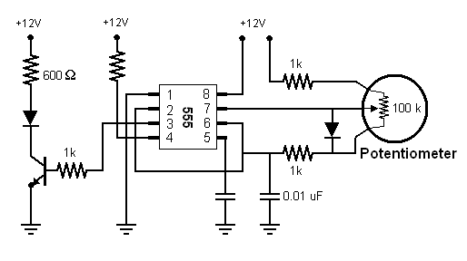
This circuit uses Pulse Width Modulation to change the LED from dim to bright
as the potentiometer is turned.
Here is a simulation
that closely resembles my circuit. I modified the capacitor so
the simulation would run slower. The graphs show the capacitor and the voltage following
the LED.
|
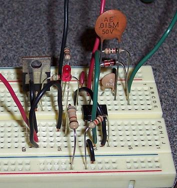
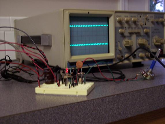
Here is a photo of the circuit. The potentiometer is connected to the black, red and green wires shown at the top of the photo.
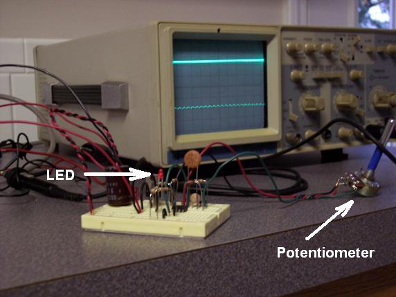
I borrowed an oscilloscope from Jason Helsabeck so I could see the pulses. I measured the pulses at
the connection of the transistor and the LED.
|
|
|
Off
In this photo, the scope shows that the value of the LED at a high, almost constant value.
When the 555 chip sends a pulse to the transistor, the transistor will allow current to pass from the collector to the emitter. The LED will light and the voltage at the junction of the LED and transistor will drop.
|
|
When no pulse is sent, the transistor prevents the flow of current through the LED. In this case, we will see a high voltage at the junction of the LED and transistor.
In this photo, we see the LED is off and the voltage at the LED-transistor junction is mostly high.
In summary, if the scope shows a pulse at the top, the diode is off; A pulse at the bottom, the diode is on.
|
|
|
Mostly Off
In this photo, we see a few more pulses at the bottom. This indicates the transistor is allowing current to pass through the diode in longer durations.
The diode appears a little brighter in this photo.
|
|
|
Half On/Off
In this photo, we see about the same amount of high pulses as low pulses. If the photo were not blurry, you might see the diode a little brighter.
|
|
|
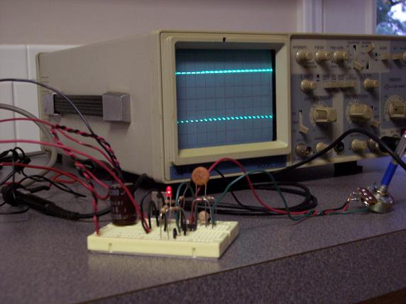
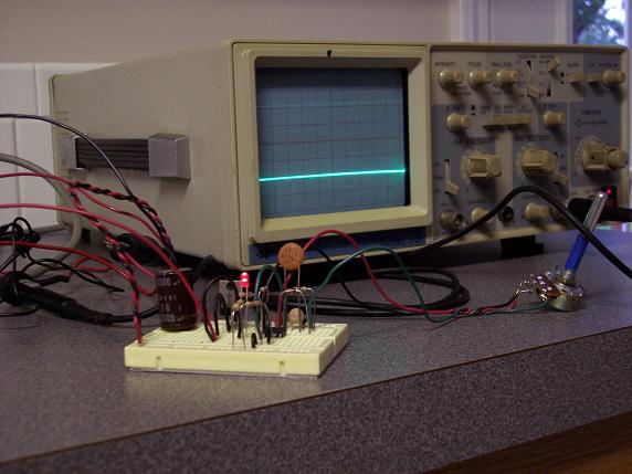
On
This final photo shows the diode fully on. The scope shows a near solid line at the bottom.
In this case, the 555 chip is sending long pulses to the transistor. The transistor is
allowing current to pass most of the time. Thus, the voltage at the junction of the transistor and LED is low (most of the time). This results in the near solid line.
|
|
|


