Construction
Jun 24, 2010
Construction
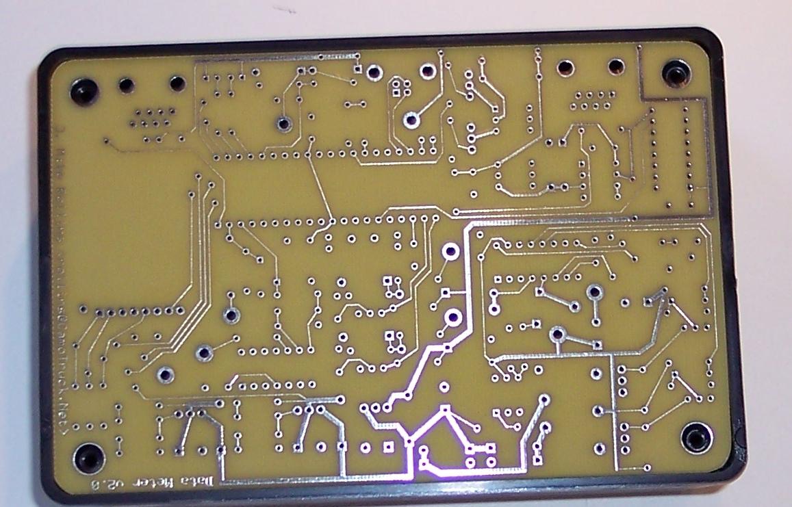
I ordered a couple of boards from
Express PCB.
I used a RadioShack project enclosure.
I had to round the corners of the board with sandpaper to fit within the enclosure.
click to enlarge/reduce
|
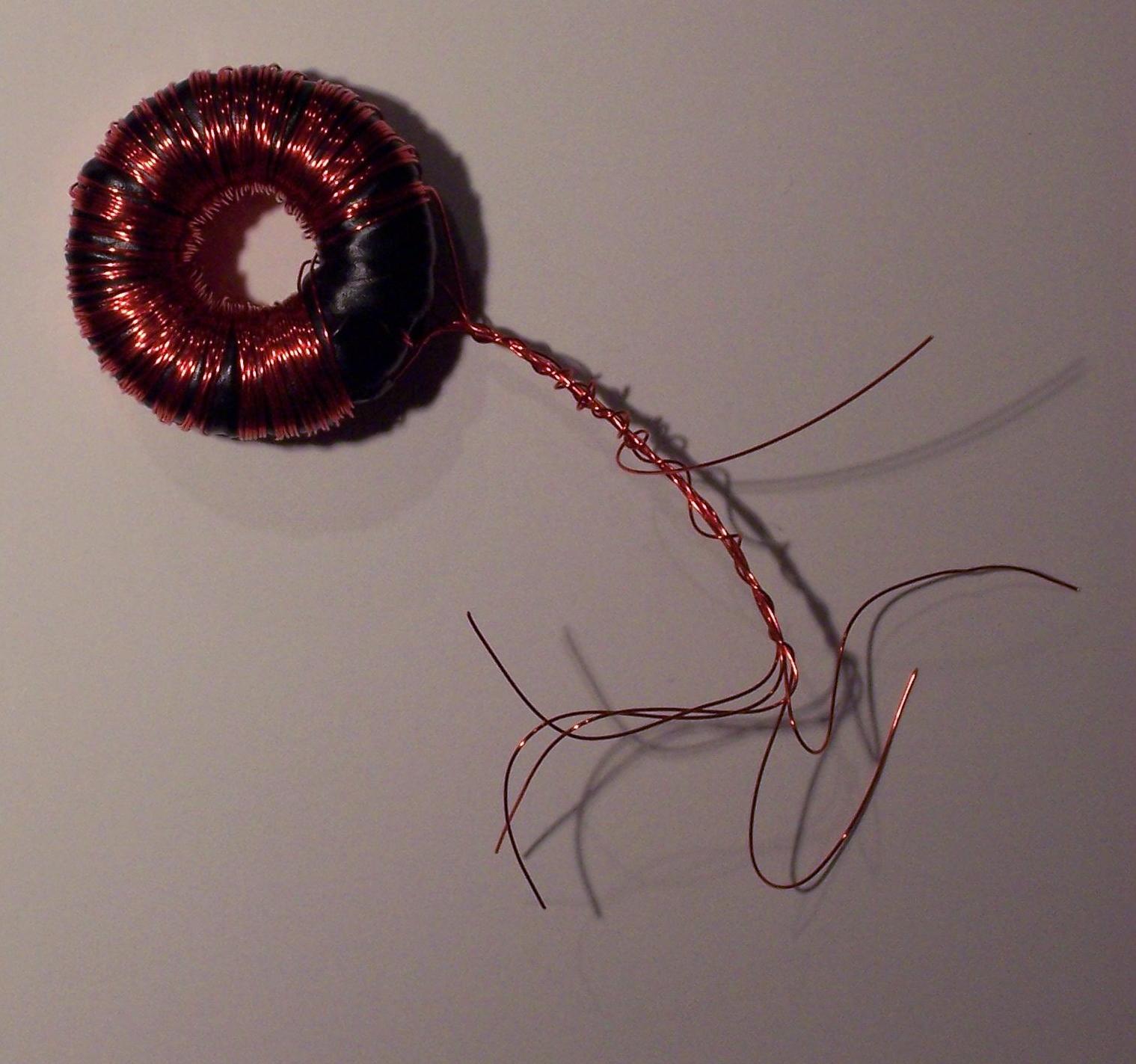
I made a transformer from a toroidal core I ordered from
Electronic Goldmine.
In this second device I have 160 primary windings with a center tap,
and 128 secondary windings.
I separated the windings with a layer of electrical tape.
This is a very tedious process and takes hours to complete.
I drilled a couple of holes in the PCB to prevent the transformer from moving around
and breaking the wires. This is included in the current PCB design.
|
click to enlarge/reduce
|
click to enlarge/reduce
|
|
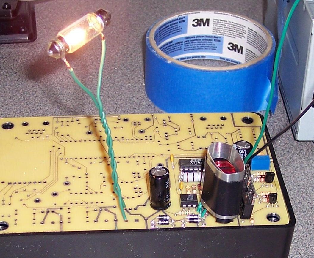
The DC-DC converter is complete in this photo.
I set the output at 12 Volts and tested this circuit using a light that draws nearly 400 mAmps.
|
|
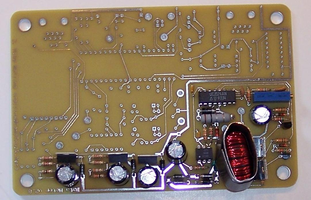
Next, I finished the power supply.
This includes three linear regulators.
A 7805 produces the 5 Volts needed for the PIC chip.
A 317 provides 3.3 Volts for the SD Card, and
another one produces 6.4 Volts for the op amp.
|
|
click to enlarge/reduce
|
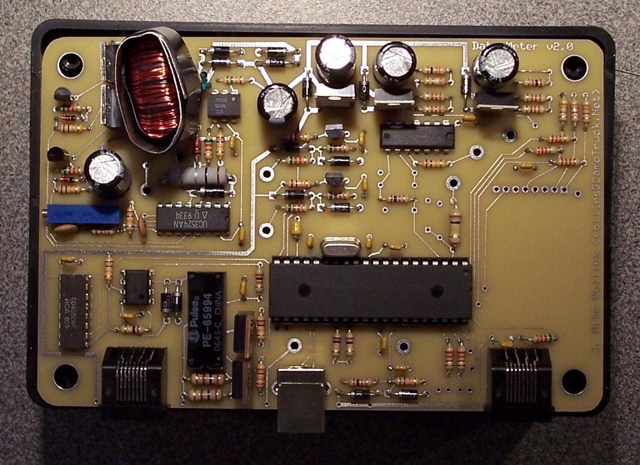
Next, I added the PIC18F4550 Microcontroller and the oscillator.
Nothing else is connected to the PIC chip except the In Circuit Serial Programming (ICSP) connections.
Since there are no circuits connected, the chip can be programed without any adverse interaction with connected circuits.
click to enlarge/reduce
|
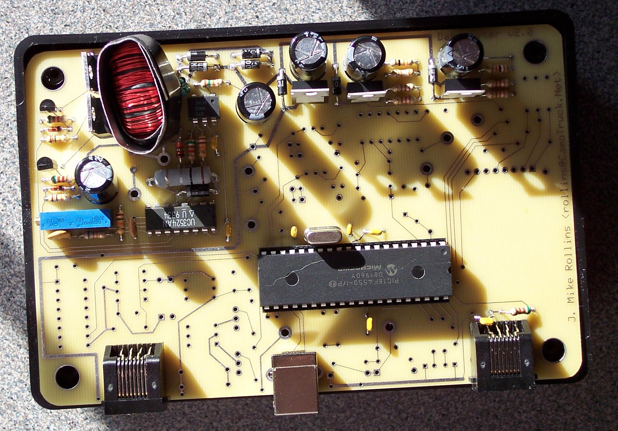
Next, I added the components for the device-to-device communications.
The lower left corder of the photo shows the differential signaling circuit.
These components are normally found in Ethernet devices.
The pulse transformer preserves the galvanic isolation.
All the components are in place with the exception of the LEDs, the SD Card and the
1% resistors for the op amp.
|
click to enlarge/reduce
|
click to enlarge/reduce
|
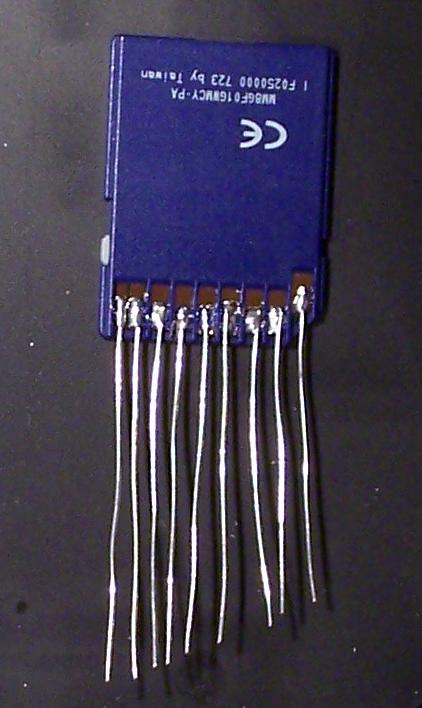
I soldered some wire onto the SD Card. I'm not sure how delicate these cards are.
So, I made sure to be quick with the solder.
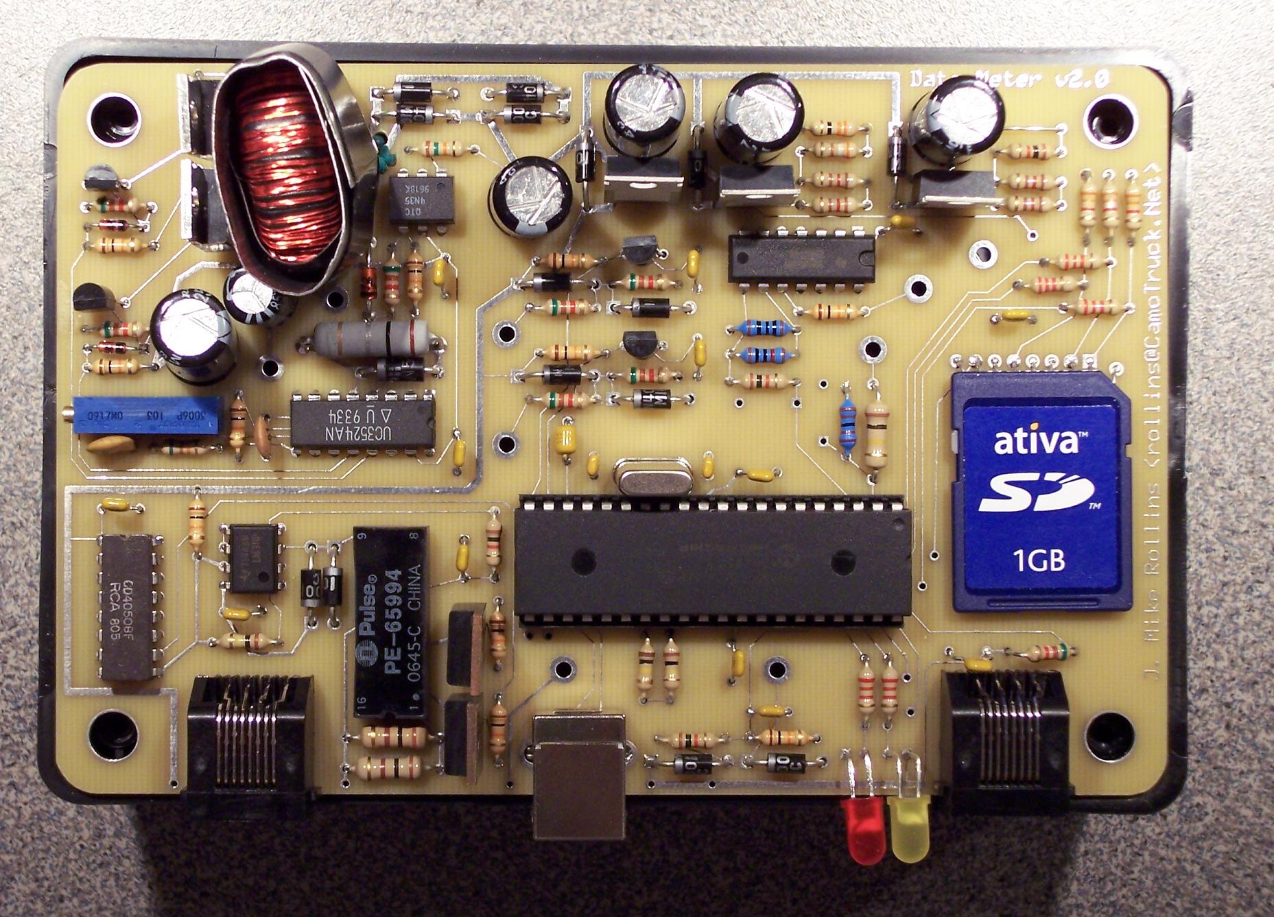
Finally, I added the two LEDs, the 1% resistors and the SD Memory Card.
|
click to enlarge/reduce
|
|
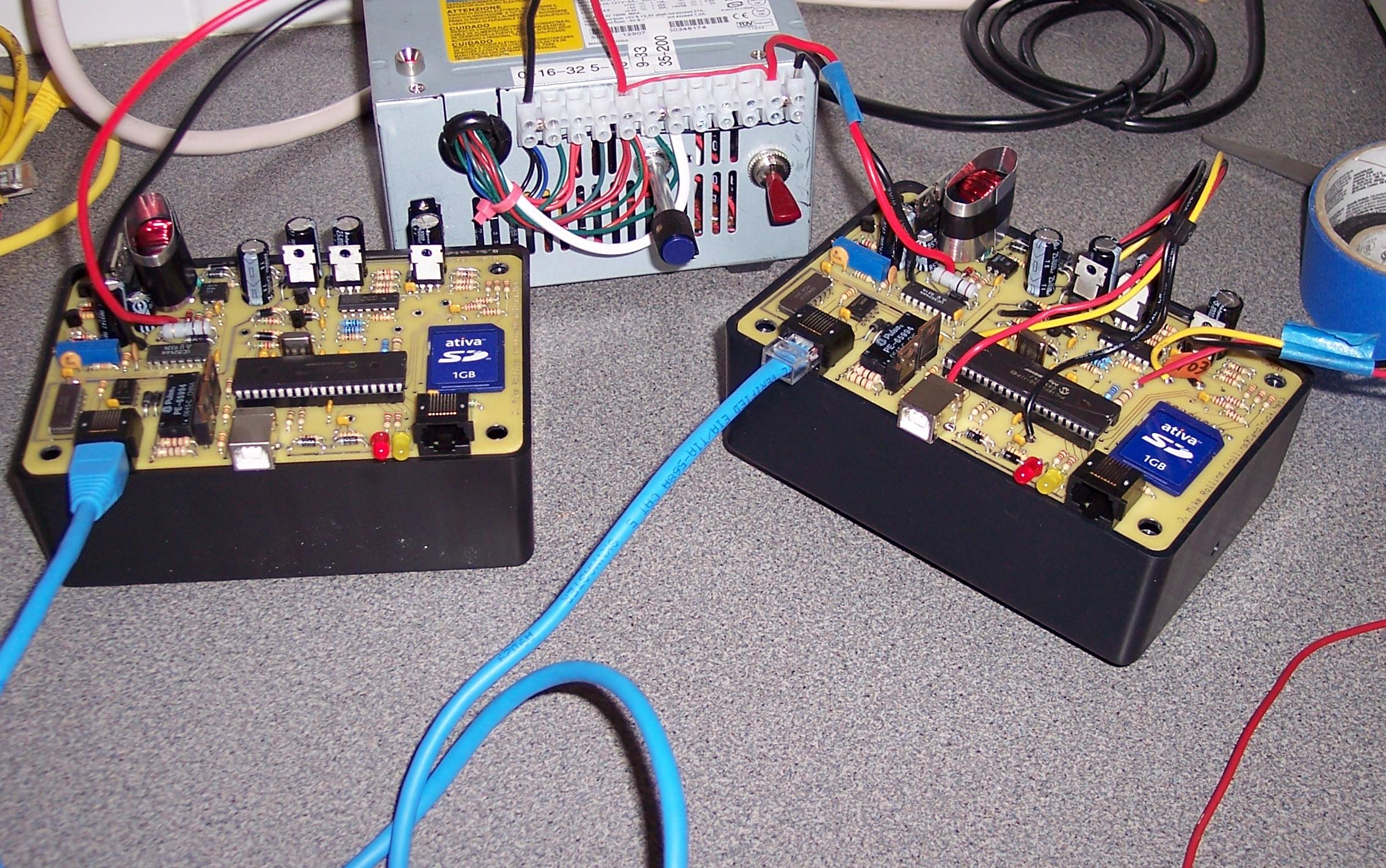
Now I can finally test the communication protocol.
I used an Ethernet cable and RJ45 connectors.
My protocol uses two pairs.
Pins 1 and 2 on one device connect to pins 7 and 8 on the other device.
|
click to enlarge/reduce
|
|
click to enlarge/reduce
|
|
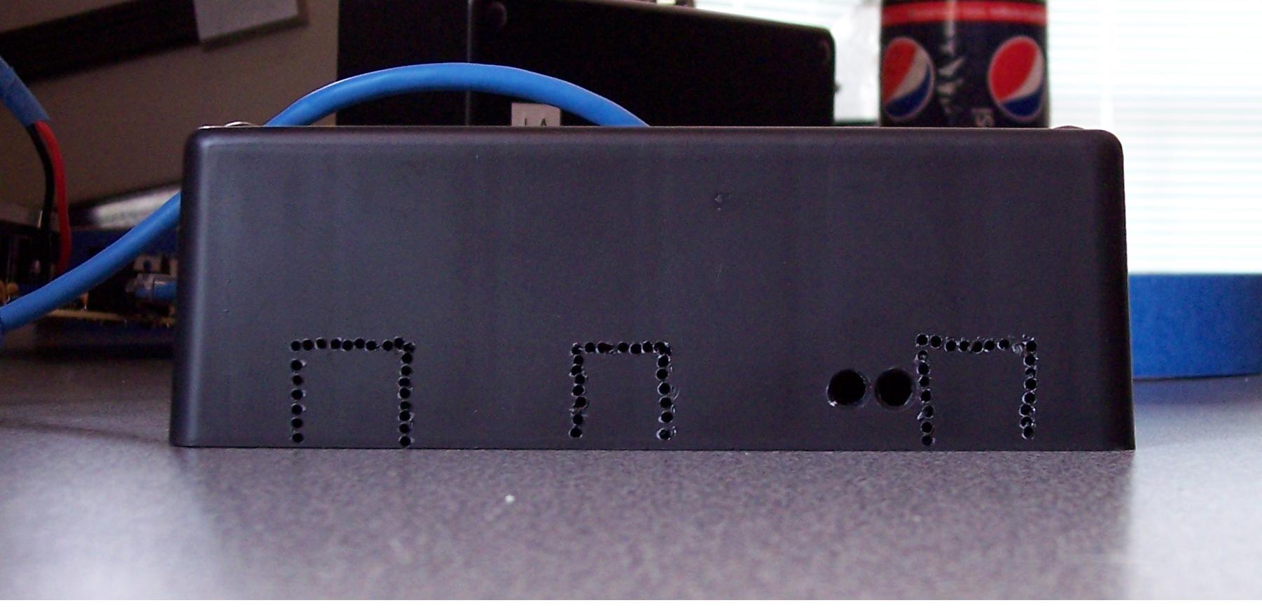
I used a drill to perforate the outline of the RJ45 and USB connectors.
I drilled holes for the LEDs and the switches.
I got a hold of some Normally Closed push buttons and spent about 45 minutes trying to
figure out why the device stopped working so suddenly!
The buttons should be N.O. (Normally Open.)
|
|
|
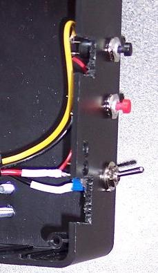
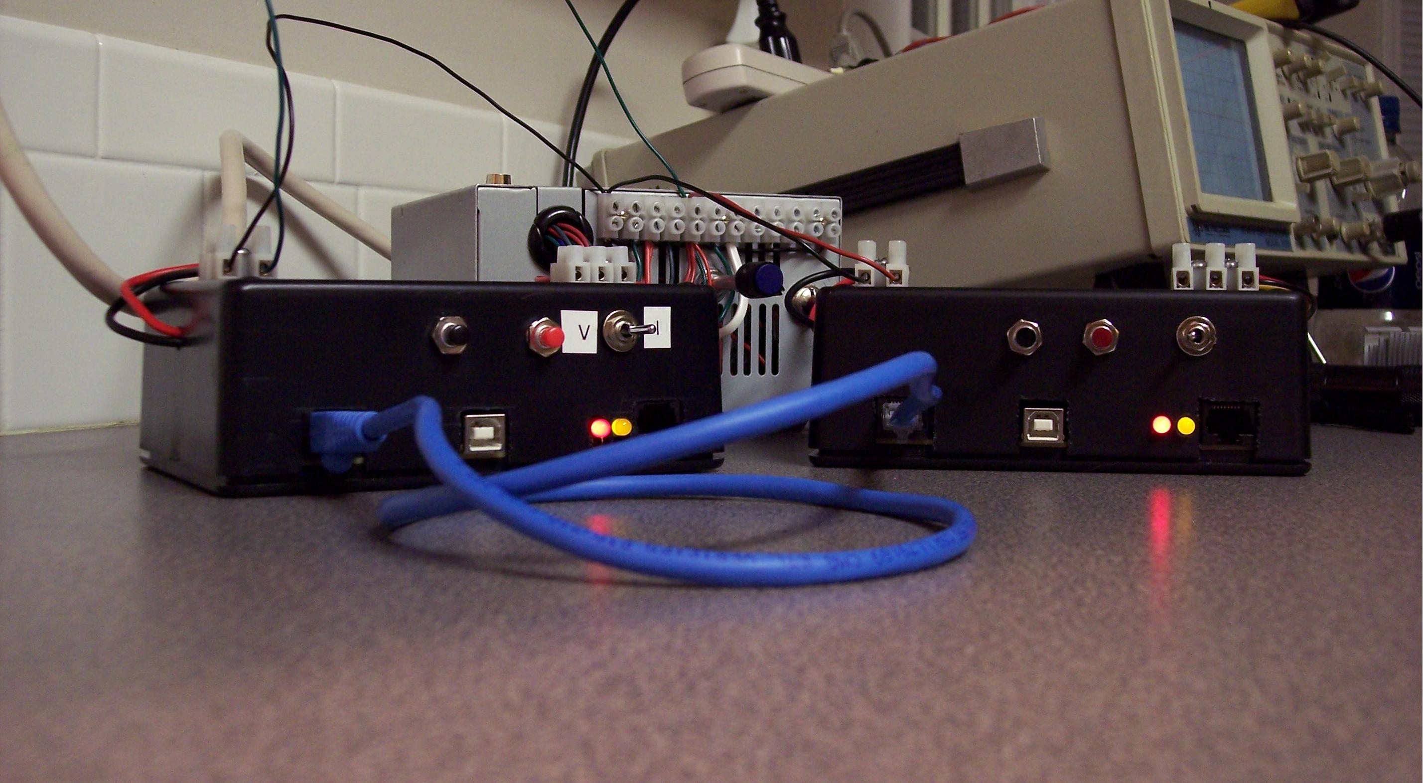
I soldered on the wires onto the board, and add the connectors to the box.
I put the device inside the enclosure and attached the bottom.
My cat was not impressed. She was more interested in a cardboard box.
In this photo, you can see the LEDs are active on both devices.
Since the cord is attached, the push of a button button on one device will result in the same action applied to both devices.
click to enlarge/reduce
|
|

|
|


