Overview
Jun 24, 2010
Data Meter
My electric truck motor started stuttering.
I'm afraid that the motor is about to fry again.
I spoke with a few people who are extremely knowledgeable about this setup.
There is no consensus about the issue.
But, everyone asked a question that I could not answer.
That is, how much power is going to the motor?
I decided to see if I could answer this question.
The basic plan is to rapidly measure the current and voltage using a PIC Microcontroller.
The data is written to an SD Memory Card and then downloaded to a Linux computer using a
custom USB driver.
DC to DC Converter
I need to measure the voltage and current at various points in the system.
This requires Galvanic isolation, so I needed to make a DC-DC converter.
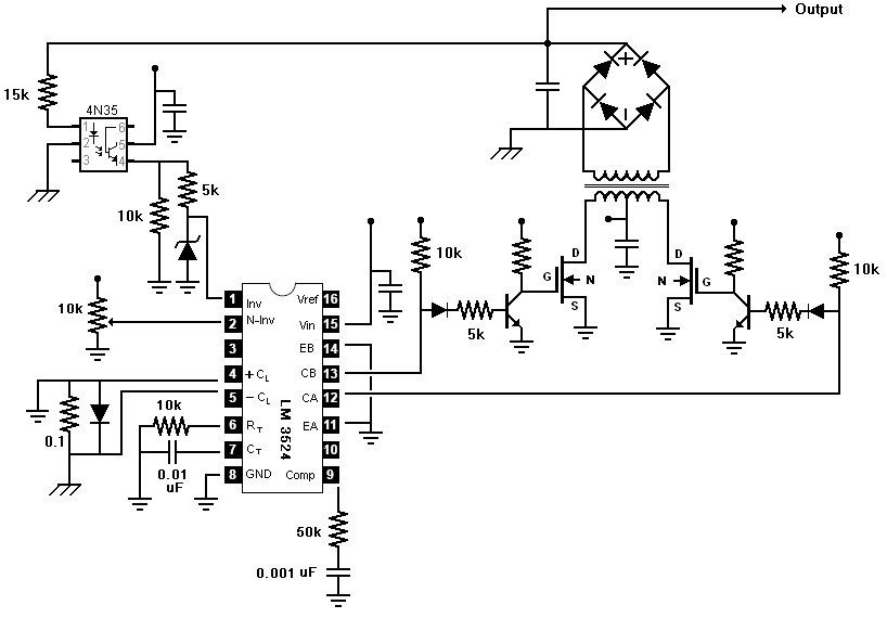
I used the LM3524 chip in a push-pull configuration.
The LM3524 has two emitter and two collector pins.
I grounded the two emitter pins as I usually do in other switching power applications.
However, I did not connect the two collectors.
Each collector connects to a transistor to invert the signal, and this output
drives an N-MOSFET connected to the transformer.
I hand-made a
toroidal transformer.
The primary windings consists of just under two hundred turns with a center tap.
The center tap connects to the voltage source.
Each leg of the primary winding connects to an N-MOSFET.
It is necessary to limit the current in this configuration.
The LM3524 chip provides a method to reduce the pulse width as the the current increases.
I added a 0.1 Ohm resistor between current limiting sense pins 4 and 5 (+/- CLSENSE).
The datasheet says the voltage drop from 4 to 5 should not exceed 0.7 volts.
So, I put a diode along the resistor to clamp the voltage drop.
Back to the transformer: I put a layer of electrical tape over the primary windings.
I added a little over one hundred turns of secondary windings.
The output is rectified and smoothed by an electrolytic capacitor.
I noticed significant electrical noise coming from the transformer, so I put a strip of aluminum foil around the transformer. This seems to help. I drilled some holes to tie the
transformer to the board. I added this feature to the PCB.
A QTC 4N35 optocoupler provides feedback to pin 1 of the LM3524, the inverting input.
Pin 2 connects to a potentiometer to set the target voltage. I set it for about 9.5 Volts.
click to enlarge/reduce
Sensors
I plan to measure the voltage and current using two separate devices.
However, each device will be capable of measuring either voltage or current.
A switch will allow me to choose which to measure.
To measure the voltage, I use a simple voltage divider.
The divider consists of a 100 kOhm and 2 kOhm resistors.
The output feeds directly into the PIC Microcontroller.
|
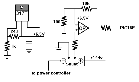
Measuring the current is a little more complicated.
The truck already has a shunt that
registers a 50 mVolt difference at 1000 Amps.
The plan is to measure this voltage difference using a PIC Microcontroller.
The 50 mVolt difference is too small to measure with good resolution.
So, I employ an op amp to magnify this to a range of 0 to 5 Volts.
I use a Radio Shack LM324 Quad Op Amp.
I only need one op amp, but the LM324 will work with a voltage range of 0 to 5 Volts.
After some testing, I realized that the op amp's maximum output was 1.5 volts less than the supply.
So, I now power the op amp with a 6.5 Volt source to get a 0 to 5 Volt output range.
This output feeds directly into the PIC Microcontroller.
I am looking into more precise op amps and the posibility of adding a filter to the op amp.
The lower end of the shunt is connected to the main ground of the circuit.
The DC-DC converter provides a floating ground, so there is little risk of
joining the 144 Volt and 12 Volt systems.
|
|
PIC18F4550
The heart of the system is a PIC Microcontroller.
The PIC18F4550 chip supports
USB (Universal Serial Bus),
SPI (Serial Peripheral Interface)
and
PWM (Pulse Width Modulation).
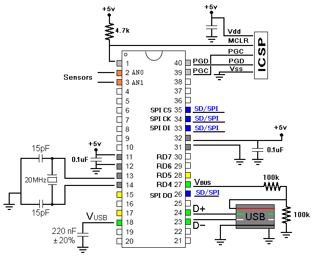
ICSP
I use a PIC Kit 3
to program the PIC18F4550 using the In Circuit Serial Programmer (ICSP). An RJ45 connector is mounted to the circuit board for this purpose. This method allows me to program the chip without taking it out of the socket.
USB
The data is downloaded using the PIC's USB module.
Micrhochip provides sample code to illustrate how to interface with the USB module.
The choice of oscillators is fairly limited when supporting USB.
I use a 20 MHz crystal.
This results in the chip operating at 48 MHz.
This is necessary for USB communication.
I wrote a Linux USB driver to interface with the device.
When attached, the Linux OS provides a virtual directory
nested inside /sys/bus/usb/drivers/.
The user downloads the data by successive reads from the file sd_data.
To keep things simple, data is sent and received in 64 byte chunks.
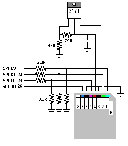
SD Memory Card
|
The SD Memory Card is able to interface with the PIC's SPI hardware.
A linear voltage regulator provides the 3.3 Volts required for the SD Card.
Only a voltage divider is need to interface the card with the PIC18F chip.
Microchip provides sample code and and API to interface with SD Memory Cards.
I did add an erase function to the API.
I also slightly modified the SectorWrite function to be a little quicker.
My current average sampling rate is 4.58 kHz.
At this rate, I should be able to get many, many hours of data on my 1GB SD Memory Card.
|
|
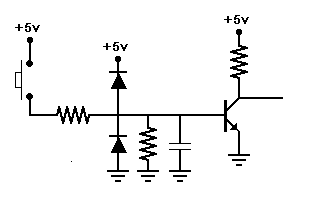
Start/Stop, Reset, Mode
I used a single momentary push button to toggle start and stop.
Another momentary push button erases the SD Card and resets the device.
A toggle switch selects between current mode and voltage mode.
I intended the actual button to be locate far away from the device.
That is, the button would be in the cab of the truck and the device located under the hood.
I designed the button to accomodate noise and voltage discharge.
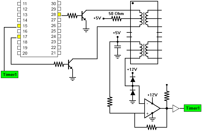
PWM
I wanted to use two separate devices, one measuring voltage and the other measuring current.
I also want to keep the two devices somewhat synchronized.
Basically, I need to stop and start them at the same time,
and I need the reset to reset both devices.
At the same time, I had to preserve the Galvanic isolation.
I thought about using optocouplers, but the operating environment is fairly noisy.
Because of the noise, I decided to go with a
differential signaling approach.
I used the Pulse Width Modulation capability of the PIC Microcontrollers to produce
a pulse wave of varying frequency and a consistent 50% duty cycle.
This is actually the opposite of what PWM is intended to do.
This signal feeds a pulse transformer that is normally used in Ethernet applications.
As with Ethernet, the signal is transmitted using a twisted pair Ethernet cable.
The receiver also contains a pulse transformer.
A voltage comparator acts as a difference amplifier and cleans
the transformer signal using hysteresis.
The output is sent to a buffer to ensure sharp pulse edges.
This clean signal is sent to the PIC Microcontroller's Timer1 module.
The Timer1 module counts these external pulses.
So, the protocol is fairly simple. The commands are simply signal frequencies.
I know there may be some issues with this protocol.
But, this is my first hardware protocol, and it seems to work.
All I really wanted to do is measure voltage and current.
I did not imagine I would end up designing a hardware protocol.
I may just use Ethernet in the future.
|


