| Disclaimer:The following are my notes. As I am learning electronics, I am making my notes available. I hope they will be of benefit. However, I do not guarantee the accuracy of my work. I recommend the reader exercise critical thinking.
|
Step 1
The following are my notes from my work with Ethernet and the PIC Microcontroller.
Step 1: Display the Current Temperature on the PIC18F4620
Display
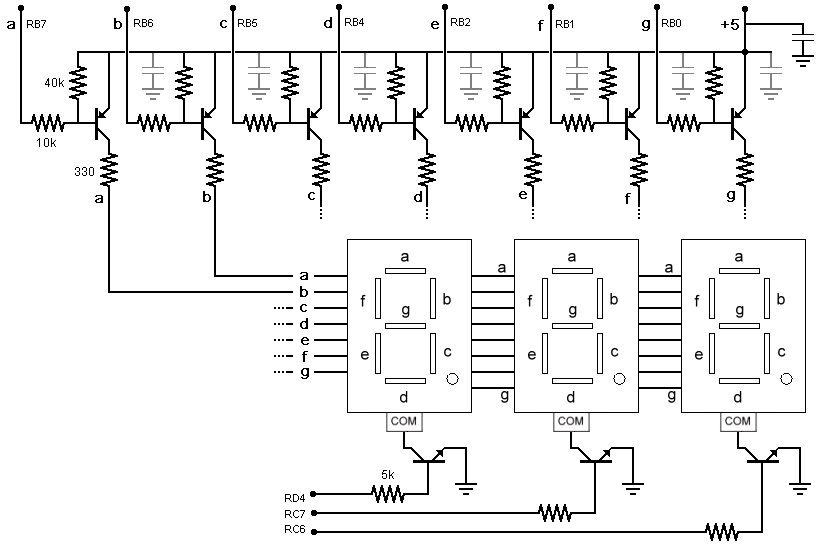
I bought three 7-Segment LED Displays from Radio Shack.
These are "Common Cathode".
A "Common Anode" version is much cheaper on-line from All Electronics.
With three of these, I can display one octet of the IP address.
The display will show each octet for about 1 second and cycle through the four octets.
This was also a good time to implement a multiplexed communication channel.
The NPN transistor at the cathode will enable or disable the display unit.
At any instance, only one 7-segment display would be active.
The main program loop will cycle through the displays.
The function mike_update_display(int value) will assign a value to the display
for values from 0 to 999. The function mike_refresh_display() cycles
through the three leds. Each iteration of my main program loop executes mike_refresh_display().
I designated 7 pins of the Microcontroller for the 7 LED segments and one pin for each display.
I added support for the decimal segment, but I don't use it with the microcontroller.
To minimize current flowing from the microcontroller, I interfaced the LED segments with a
transistor.
Using these transistors, the controller delivers only 0.5 mAmps to drive a segment of the display.
Each segment would require 5 mAmps or more per segment if driven directly from the controller.
The the common cathode transistor still triggers with 5 mAmp.
I added a few capacitors to minimize noise. I may have gone a little overboard with the capacitors.
click to enlarge/reduce
Here is the code for the display:
led.h and
led.c
Temperature Sensor
|
I order a few MCP97000 Temperature Sensors from Microchip.
These are low power, linear and accurate.
This device has three pins: one ground, one +5v and one output.
Given the output voltage V in mVolts, the temperature in Celsius is (V-500)/10.
I used a bypass capacitor to reduce noise.
In this code, I only need to enable ADC_CH0. The other channels were left over from
previous projects.
|
  OpenADC(
    ADC_FOSC_64 // Book page 98, max value for 20 MHz
    & ADC_RIGHT_JUST //Results in least significant bits
    & ADC_20_TAD, // collection time interval
    ADC_CH0 & ADC_CH1 & ADC_CH2 // CH0=AN0 (pin 2), CH1=AN1...
    & ADC_INT_OFF // not interrupts (use polling)
    & ADC_VREFPLUS_VDD // use +5 for reference voltage
    & ADC_VREFMINUS_VSS, // use 0 for reference
    12 // bits 0 through 3 of the ADCON1 register
  );
|
Wall Clock
Timer1 serves as a wall clock to signal the update of the display value.
I used an 8 MHz oscillator along with the HSPLL option yielding a 32 MHz clock.
With a 16 bit number we have 65536 values. The T1_PS_1_8 causes the
timer to increment each 8 instruction cycles. An instruction
cycle takes 4 clock cycles.
I used Timer1 since Timer0 is used by the Ethernet TCP/IP libraries.
Timer1 allows a max post-scale of 1:8. I enabled interrupts for Timer1 so each overflow of
Timer1 will execute a bit of code that will count the number
of overflows (tmr1_count).
In previous work, I had to manually enable the interrupts. I'm not sure if this
is still necessary
|
  OpenTimer1(
    TIMER_INT_ON &
    T1_SOURCE_INT &
    T1_16BIT_RW &
    T1_PS_1_8 &
    T1_OSC1EN_OFF &
    T1_SYNC_EXT_OFF
  );

  INTCON=0;  //make sure interrupts are disable
  INTCONbits.GIE=1;  //enable global interrupts
  INTCONbits.PEIE=1;  //enable peripheral interrupts
  PIE1bits.TMR1IE = 1;  //enable timer 1 interrupts
|
|
When the tmr1_count exceeds tmr1_trigger the
tmr1_cycle_flag will be set. My main program loop examines this
flag with each pass. This will trigger the update of the display value
at about 1.3 second intervals.
| 8 MHz oscillator with HSPLL | = 32 MHz |
| One instruction per 4 clock cycles | = 8 MHz |
Increment timer value each 8
instruction cycles (T1_PS_1_8) | = 1 MHz |
| 65536 ticks at 1 MHz | = 65,536 ticks / (1,000,000 ticks/second) |
| tmr1_trigger = 20 | = (20 * 65,536 / 1,000,000) second |
| | = 1.3 second |
|
void HighISR(void)
  {
    if (PIR1bits.TMR1IF)
      {
        tmr1_count++;
        if (tmr1_count >= tmr1_trigger)
          {
            // set the flag for the main program
            tmr1_cycle_flag = 1;
            tmr1_count = 0;  // reset the counter
          }
        PIR1bits.TMR1IF = 0;  // clear the interrupt
      }
  }
|
LED Display and Temperature
As a good test of this new chip, I attempted to show the current
temperature on the new display.
The main program is a loop. The temperature reading is divided into phases.
This approach will work well with the cooperative multitasking
used in the Ethernet processing.
The display update is also done in phases.
Each time through the loop, one of the three 7-segment display units is refreshed.
The following explains the temperation value derivation:
The The Analog/Digital converter produces a value from 0 to 1023.
This represents a scale for the 5 volt source. Let value
represent the reading from the AD converter. The voltage is calculated
by the expression 5*value/1023. Multiply this by 1000 to obtain
the value in milivolts. We substitute this into the MCP 7900 conversion equation that
maps voltage (in milivolts) to Celcius: C = (5000*value/1023 - 500)/10.
Converting to Fahrenheit, we have F = (9/5)(5000*value/1023 - 500)/10 + 32.
Simplify yields F = 900*value/1023 - 58. This is the
equation I use to convert the AD value to Fahrenheit.
Here is the code for the main program and display:
main.c,
led.h and
led.c
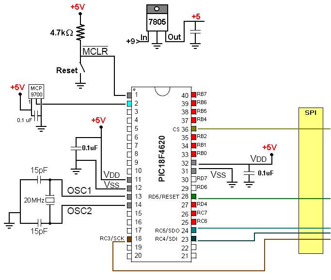
Here is the schematic for the Microcontroller. The display (shown above) is connected
to pins RB7, RB6, RB5, RB4, RB2, RB1, RB0, RD4, RC7 and RC6.
Later, the pins for the SPI bus will be used in the Ethernet connection.
click to enlarge/reduce
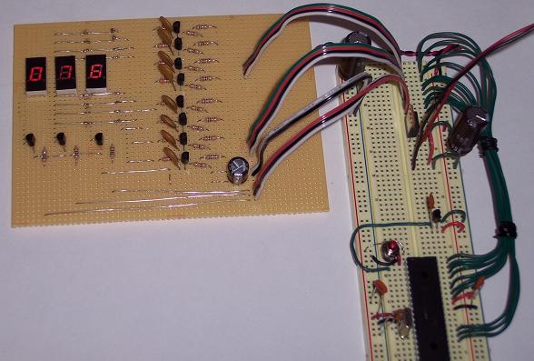
Here is the photo of my temperature display system showing 76 degrees F. Put your mouse
over the LEDs, the PNP transistors or the temperature sensor for a close-up image.
Step 2: Add the Ethernet hardware and the TCP/IP server code.
|


