| Disclaimer:The following are my notes. As I am learning electronics, I am making my notes available. I hope they will be of benefit. However, I do not guarantee the accuracy of my work. I recommend the reader exercise critical thinking.
|
Step 2
The following are my notes from my work with Ethernet and the PIC Microcontroller.
Step 2: Add the Ethernet and TCP/IP Server
click to enlarge/reduce
Ethernet
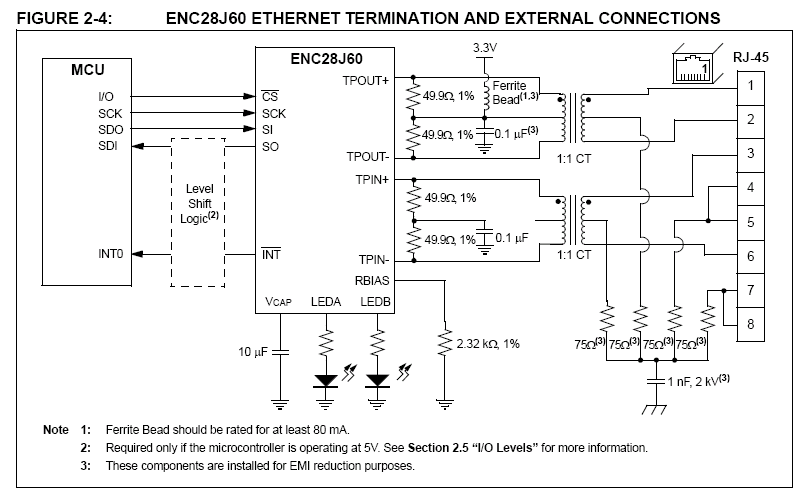
The schematic at the begin of this page (figure 2-4 from the datasheet) shows some of the necessary connections
for the ENC28J60 chip. In addition to this, you will need to connect a few of
the pins to 3.3 Volts and ground. Each of these pairs will require a 0.1 uF
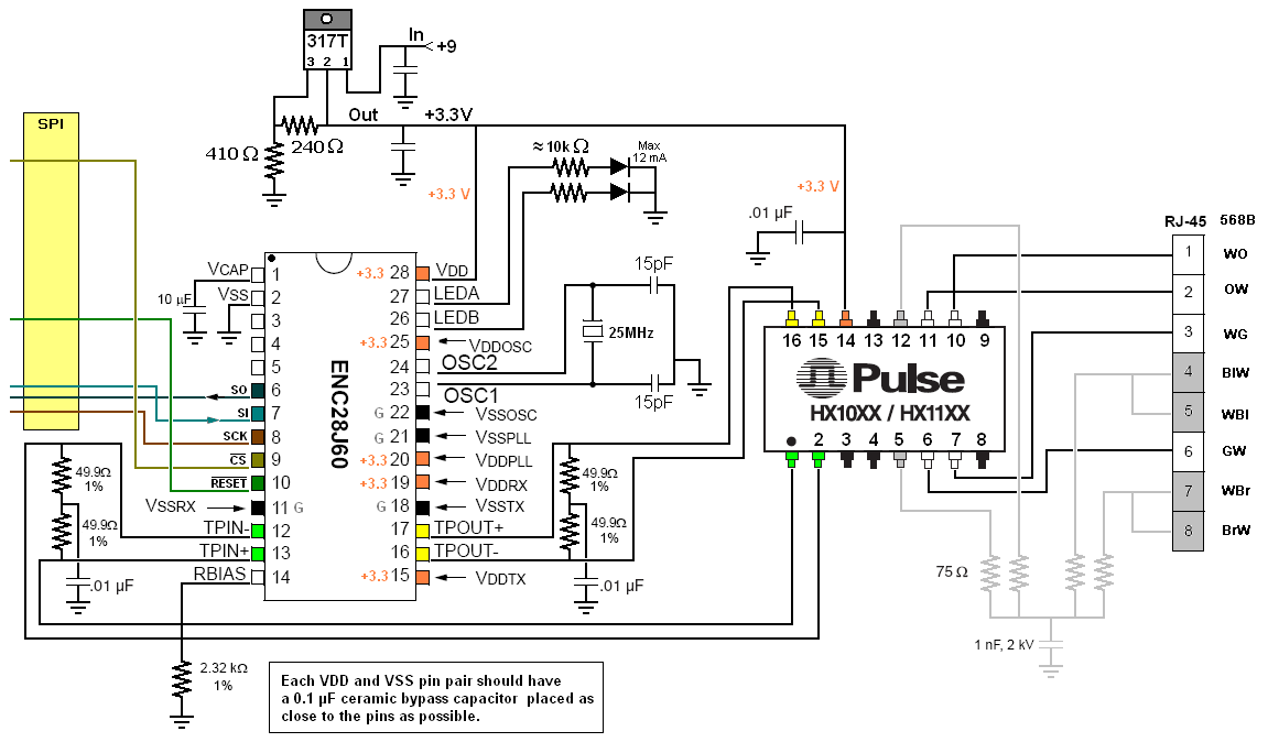
bypass capacitor. The following figure shows my schematic for the Ethernet
portion of my circuit.
Update: I still don't have a good understanding of how the transformer is to connect to the ENC20J60. I've tested a few different transformers and found many connection diagrams. However, they all seem a little different. I don't know if there is a good standard. I'm open to suggestions.
click to enlarge/reduce
 I updated the
 HardwareProfile.h file with the appropriate pin designations for
the SPI bus of the PIC18F4620 chip. The YOUR_BOARD section contains these
settings; However, for the PIC18F chips, the clock information will be defined on line
152. You should comment out one of these clock sections and update the other.
Using an 8 MHz oscillator with HSPLL, I set the GetSystemClock() value to
32000000ul (32 MHz).
#elif defined(YOUR_BOARD)
// Define your own board hardware profile here

  // For the PIC18F chip, these are also defined on line 152
  #define GetSystemClock()      (32000000ul)
  #define GetInstructionClock() (GetSystemClock()/4)
  #define GetPeripheralClock()  GetInstructionClock()

  // ENC28J60 I/O pins
  #define ENC_RST_TRIS  (TRISDbits.TRISD5)
  #define ENC_RST_IO    (LATDbits.LATD5)
  #define ENC_CS_TRIS   (TRISBbits.TRISB3)
  #define ENC_CS_IO     (LATBbits.LATB3)
  #define ENC_SCK_TRIS	(TRISCbits.TRISC3)
  #define ENC_SDI_TRIS	(TRISCbits.TRISC4)
  #define ENC_SDO_TRIS	(TRISCbits.TRISC5)
|
Here is a brief overview of the files in my project.
| Ethernet and IP provided by Microchip |
| Compiler.h |
Includes various macros and header files for the specific chip. |
| GenericTypeDefs.h |
Includes macros for data types such as BYTE and UINT32. |
| HardwareProfile.h |
If you are using a prototype board, this would provide
information about this particular board. However, I'm
not using one of those.
|
| TCPIPConfig.h |
Provides default IP address and some memory information for the TCP implementation.
|
| spi_clos.c spi_dtrd.c spi_gets.c spi_open.c spi_puts.c spi_read.c spi_write.c |
Handles the SPI communications.
|
| ENC28J60.c/h |
Uses the SPI bus and handles the Ethernet functions.
|
| Helpers.c/h |
A collection of formatting functions useful in various IP based communications.
|
| t0close.c t0open.c t0read.c t0write.c and Tick.c |
Timer0 serves as a clock. |
| IP.c/h MAC.h ICMP.c UDP.c TCP.c TCPIP.h |
Protocol implementations. |
| ARP.c/h DHCP.c ICMP.c |
My application responds to ARPs, responds to Ping packets and is a DHCP client.
|
| StackTsk.c/h |
Interfaces the higher layer protocols to the lower hardware layer.
|
| My additional files |
|
MyTCPServer.c
MyTCPServer.h
|
My TCP server. |
| main.c main.h |
Main program |
|
led_disp.c
led_disp.h
|
Driver for my 7-segment display unit. |
| adcbusy.c adcopen.c adcread.c |
Allows reading of temperature sensor. |
| t1close.c t1open.c t1read.c t1write.c |
Timer1 provides timing for my application. |
|
TCPIPConfig.h
I enabled only two of the Application Options:
STACK_USE_ICMP_SERVER and STACK_USE_DHCP_CLIENT.
My TCP server is modeled after the generic tcp server example,
but I did not want to enable that module.
To enable the proper objects, I did have to explicitly add
#define STACK_USE_TCP to the Application Options.
I also customized the values for MY_DEFAULT_MAC, MY_DEFAULT_IP_ADDR, MY_DEFAULT_MASK and
MY_DEFAULT_GATE.
My Web Server
Here are my
main.c,
MyTCPServer.c and
MyTCPServer.h files.
I configured RD3 as an input pin to
help with debugging. When this pin is high, the temperature will be displayed.
When the pin is low, the IP address is displayed.
I use a 4K resistor to toggle this display.
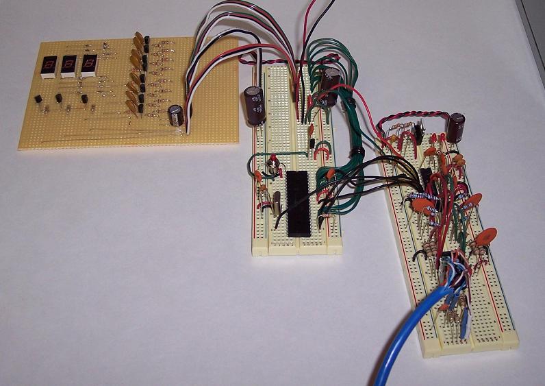
In the following photo, the display unit is on the left,
the PIC18F4620 is on the middle board, and
the ENC28J60 is on the right board.
A single 12 volt source supplies both boards.
The PIC board uses a 7805 to provide the 5 volt source.
The ENC28J60 board uses an LM317 to yield a 3.3 volt source.
Five short black wires form the SPI communication link between the two boards.
You can see a close-up of various parts of the board by moving the mouse over them.
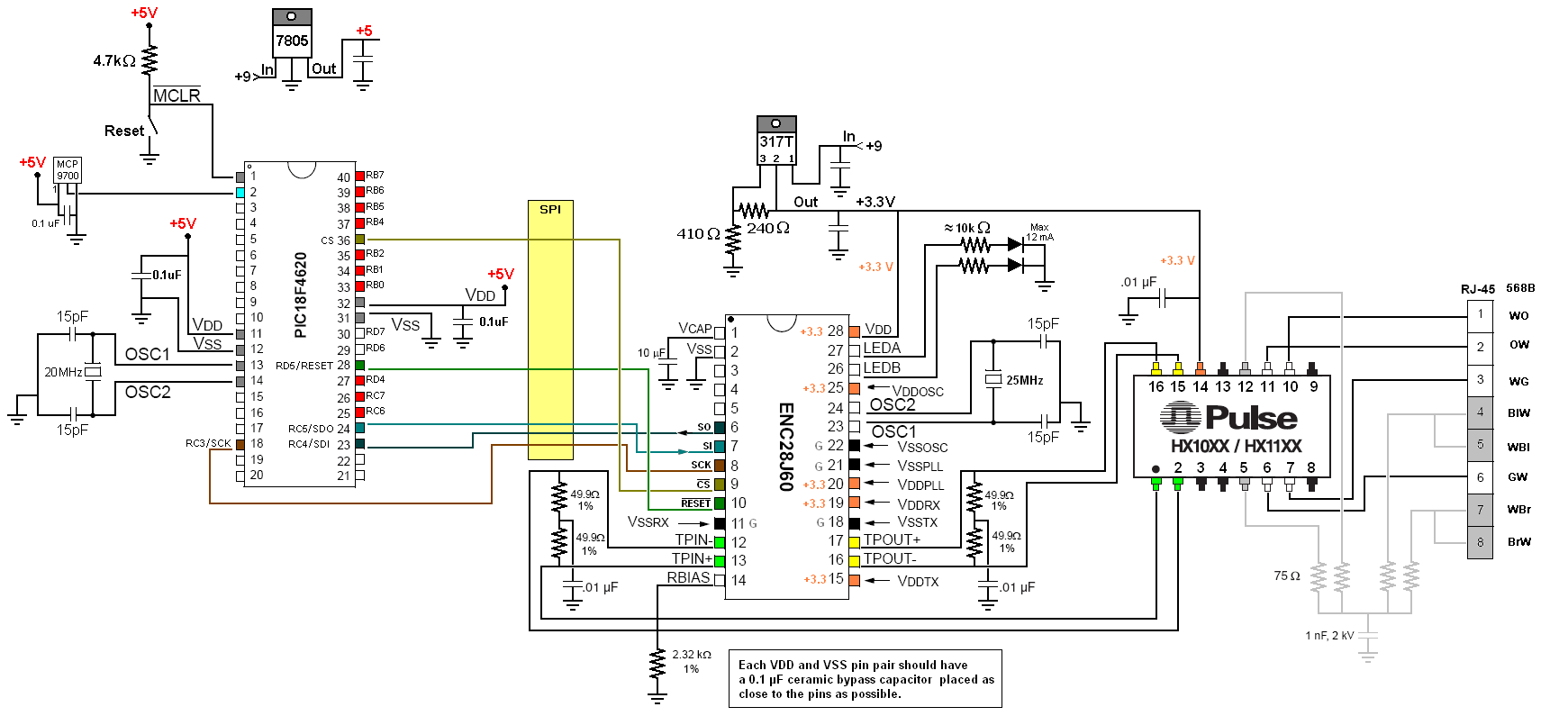
 Here is the schematic of the PIC board and the Ethernet board.
click to enlarge/reduce
Here is the schematic of the PIC board and the Ethernet board.
click to enlarge/reduce
|


