AC Inverter
April 4, 2010
The Project
A few months ago, I got the idea to make an AC Inverter for my truck.
I've learned a lot about making power supplies.
I have not put much on the web since this is potentially dangerous.
My truck has a 144 Volt battery bank that can deliver over 600 Amps.
During this process, I've seen a few components explode and vaporize.
I've found phenomena such as inrush current to be problematic.
Here are some of my notes along the way. I will post more later.
Basic Idea
|
The battery supply can range from 170 volts to 110 volts.
The basic idea for my inverter is to buck the source voltage down to 100 volts and then boost it up to 140 volts.
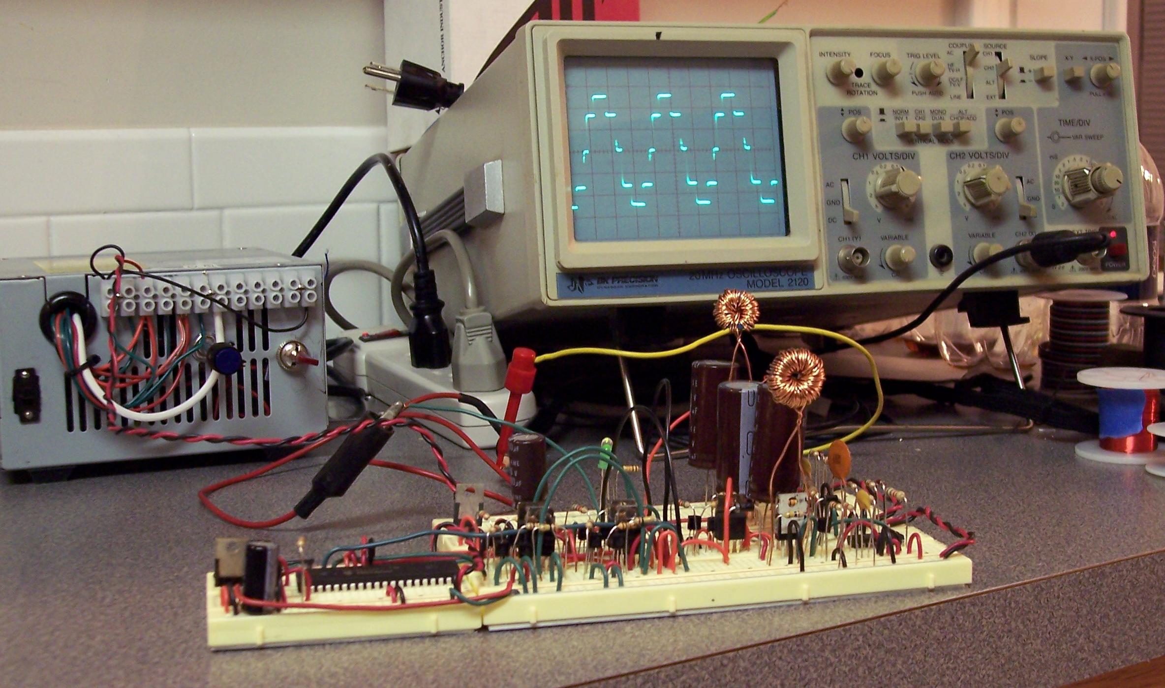
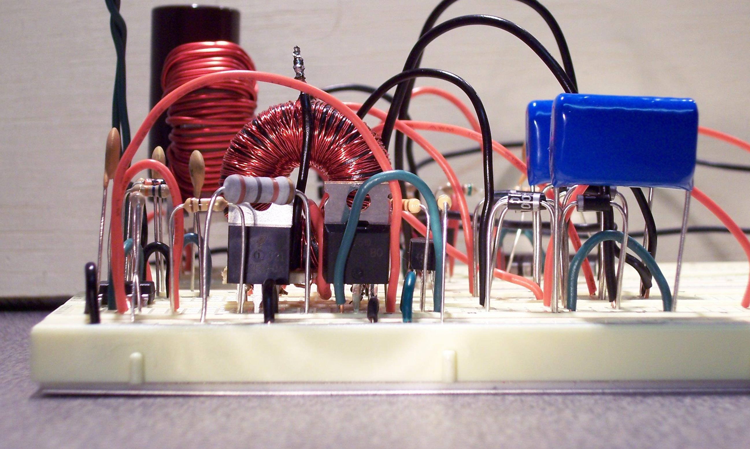
A Microcontroller will produce a modified sine wave signal to draw power from the 100 and 140 volt supply. Here is a photo of an early prototype operating from a 32 volt source:
|
click to enlarge/reduce
|
LM3524
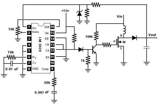
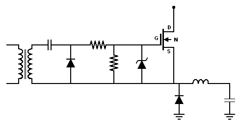
I had previous experience with the LM3524 chip, so I decided to base my design on this chip. The basic Buck and Boost Pulse Width Modulation (PWM) circuit designs are show here:
|
Buck
|
Boost
|
click to enlarge/reduce

|
click to enlarge/reduce
|
|
Low Voltage Supply
This power supply operates with two main voltage systems.
The High voltage system which is in the range of 100 to 200 volts.
The low voltage system is 5 to 20 volts.
The low voltage operates the integrated circuits.
I decided to use an addition PWM regulator to generate the low voltage supply.
It was challenging to determine how to run the system directly off of the battery bank.
As of now, I'm using a linear regulator to take the 144 volt source and provide 18 volts at startup.
This regulator is disabled when the low voltage PWM regulator is ready.
The current version dissipates a lot of heat through transistors.
I'm looking into methods of offsetting this power loss to resistors.
Max Vgs
Working with 12 to 16 volts, I never had to worry about the MOSFET's Vgs parameter.
This value is generally around 20 volts and represents the maximum voltage allowed between the MOSFET's Gate an Source.
When operating over 20 volts, you must be careful not to exceed this value.
In a voltage boost circuit, the N-MOSFET's Gate is switched between ground an some value over 10 volts but under the max Vgs.
Since the Vgs value is 20 for many of my MOSFETs, I decided to use +18 volts for my low voltage system.
I can now use the full positive value on the Gate and not worry about raising the Vgs above the max value.
A simple Buck circuit uses a P-MOSFET. If the source voltage were 180 volts, then the gate cannot fall below 160 volts without damaging the MOSFET. I used many Zener diodes to maintain this Vgs value.
Slow Startup
I wanted to limit the inrush current.
I experimented with the current limiting features of the LM3524 chip.
However, I did not know how I could apply this to all the areas where inrush current could be problematic.
I tested the idea of pre-charging the capacitors using a resistor, but this wasted a lot of power.
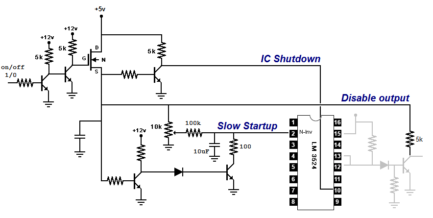
I then decided that each instance of the 3424 circuit would slowly increase the output voltage until reaching the target voltage. This was achieved using a resistor and capacitor on pin #2, the non-inverting input.
The startup circuit has an enable/disable input and an output that must be on for the MOSFET to operate (a disable feature).
click to enlarge/reduce
Modules
It was daunting to maintain all the components on a prototyping bread board. When something did not work right, I could spend minutes looking for the problem just to find that the legs of two resistors were touching.
So, I began making modules of systems that I felt comfortable with.
My first module was the linear 200 to 18 voltage regulator.
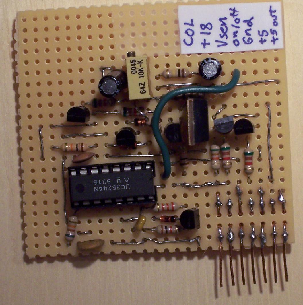
The second module was an LM3524 switching setup with the slow-startup circuitry.
Now, I can plug this into the breadboard and quickly setup a power circuit. I only need to focus on the power stage.
click to enlarge/reduce
Current Limiting
I tested the current limiting feature some. Will have to come back to it later.
Bucking: P or N
I kept burning out the P-MOSFETS.
It was recommended that I use N-MOSFETS for a buck converter instead of P-MOSFETS.
This requires careful planning.
For example, take a buck converter with an N-MOSFET in the place of the P-MOSFET.
The voltage of the N-MOSFET's Source pin varies wildly.
The max Vgs parameter specifies that the Gate voltage cannot exceed the Source by more than 20 volts.
Additionally, the Gate needs to be at least 10 volts higher than the Source to fully open.
So, the Gate voltage has to be adjusted to keep in sync with the varying Source pin's voltage.
There are a few methods to accommodate for this arrangement.
Isolated +18 Volt Systems
My first test of this idea used a Transformer Gate Drive. It seemed to work well, but it did not look good on the oscope.
Additionally, I observed a spike in output voltage when I abruptly removed a large load from the circuit.
I still don't understand how the pulse width is to be maintained with this design.
click to enlarge/reduce
|
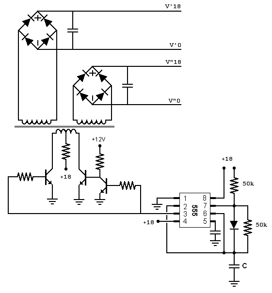
My second test used an isolated power supply. There are two bucking circuits in my design, so I would need two isolated power supplies. I began this venture by making a transformer. I wound one wire around a toroid core for about 80 turns and covered this with electrical tape. I made a second pass with another wire for 80 turns. The third pass forms a center tapped winding with a total of 160 turns (80+80=160).
I configured a 555 chip to provide a 50% duty cycle pulse.
I connected the center tap to the +18 voltage supply using a 100 Ohm resistor. Each leg of this primary winding is connected to an N-MOSFET. The pulses from the 555 alternately drive the N-MOSFETS to ground the transformer legs.
The two inner windings of the transformer feed a diode bridge rectifier and then a capacitor. I achieve about 18 volts DC at the capacitor -- the same value I started with. This setup gives me two, galvanically isolated, 18 volt DC power supplies.
click to enlarge/reduce
|
click to enlarge/reduce
|
MOSFET Drivers
Next, I had to learn about various MOSFET drivers.
A good reference is
Design And Application Guide For High Speed MOSFET Gate Drive Circuit By Laszlo Balogh.
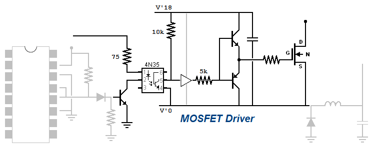
I set the 0V of my isolated 18 volt system to the Source of the N-MOSFET of the buck converter.
This gives me a solid, +18 volts relative to the Source. I use an an Optocoupler to interface this floating 18 volt supply with the LM324. Unfortunately, the optocoupler's on/off process does not provide a sharp on/off pulse.
So, I filter this signal through a Hex Buffer to transform it into a sharp switching signal.
The Hex Buffer actuates an
NPN/PNP Totem Pole to drive the N-MOSFET.
This seems to be a very stable design.
 I have some IC MOSFET drivers on order.
Apr 14, 2010
I love the MOSFET drivers. I destroyed a few of them, but they do produce nice, sharp pulses.
I had an epiphany today. Over the past few months, I played with the current limiting feature of the LM3524.
I used this on one part of the inverter. My design had multiple switching circuits.
I could not figure out how to implement current limiting on the other two.
The issue is that the current sensing resistor separates the system from the ground.
If I have three circuits using current sensing resistor, then I have three different ground references
that are not galvanically isolated. This was my epiphany. I realized that if they were galvanically isolated
then I would have no problem joining the systems together. So, I now have a greater appreciation of the
topologies that incorporate transformers.
I will have to trash my old designs. But, I learned a lot over the past few months. If this were easy, then it would not be interesting.
I began to study transformers a few months ago, but I was a little intimidated.
It is amazing that two coils of wire can be so complicated.
Now, with a greater appreciation for galvanic isolation,
I will resume my exploration of switching topologies using transformers.
|


