| Disclaimer:The following are my notes. As I am learning electronics, I am making my notes available. I hope they will be of benefit. However, I do not guarantee the accuracy of my work. I recommend the reader exercise critical thinking.
|
Microcontroller
June, 2008
A month ago, I decided to make a USB device.
This has not been easy. These pages on the 16F and 18F
microcontrollers contain a summary of what I found.
I hope these pages will help you with your first USB project.
I started my project by searching for USB devices on the web.
I found that a specific Microcontroller supported the USB protocol.
So, my first task was to learn about microcontrollers.
Microcontrollers: PIC16
|
Microcontrollers are basically scaled-down computers.
They have an Arithmetic Logic Unit, program memory, memory stack, registers and
an all-out assembly instruction set.
Instead of a monitor and keyboard, they have many pins and ports that can be configured various ways.
Many companies produce microcontrollers.
I went with the PIC18F4550 Microcontroller from Microchip. But, let's start with the PIC16F84A.
|
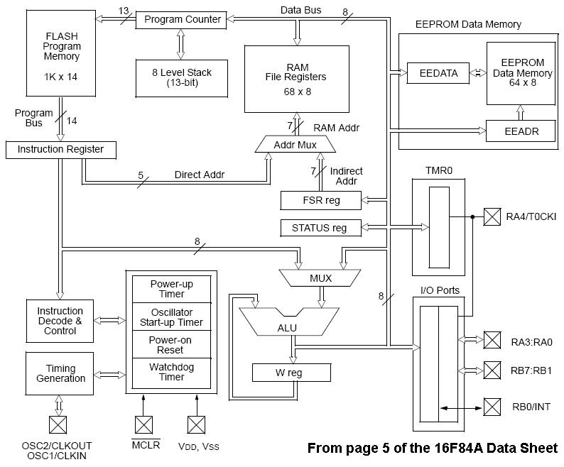
Here is a block diagram of the PIC16F84A microcontroller chip.
(click to enlarge)
|
You will need a few items to begin working with microcontrollers.
I purchased the PICSTART Plus Part Number: DV003001 kit from Microchip.
This kit includes the following:
- A sample PIC16F84 microcontroller chip:
My kit actually came with a PIC16F84A chip. This is a 18 pin, 8-bit chip.
The PIC16F84A data sheet
is only 88 pages. So this is easier than the 18F chip.
But the 16F chips do not support USB.
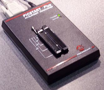
- The programmer unit:
This is the device that will write the program to the chip. This will interface with a
computer's serial port. On newer computers, you may need an additional
USB to Serial Converter.
I am able to use this programmer for the 18 pin PIC16F and the 40 pin PIC18F chips.
- Compiler, Assembler and IDE.
The kit comes with a copy of the MPLAB IDE. This provides a development environment for many
different chips and supports C and Assembler programming languages. The IDE contains a simulator
and a debugger.
|
|  |
While you wait for the kit to be delivered, I would recommend reading the
PIC16F84A data sheet.
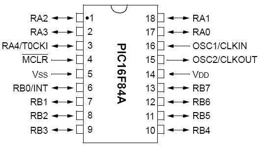
You will need to review the pin configuration on page 3. Make special note of the following:
| Pin Name | Pin Number | Description |
| MCLR | 4 | Master Clear Reset |
| Vss | 5 | Ground |
| Vdd | 14 | Positive |
| OSC2 | 15 | Oscillator crystal output |
| OSC1 | 16 | Oscillator crystal input |
|
|
 |
In addition to the above, you will also need some basic electronics components.
You will need an oscillator circuit.
Section 6.2 covers the oscillator configurations.
The 16F84A chip has four possible oscillator configurations:
LP Low Power Crystal, XT Crystal/Resonator,
HS High Speed Crystal/Resonator and RC Resistor/Capacitor.
A typical oscillator circuit uses a crystal and two capacitors ranging from 15 pF - 33 pF.
You can get the crystal and capacitors
from The Electronic Goldmine.
You will need a breadboard, a IC Extraction Tool, a 5 volt regulator (7805), some LEDs and resistors.
I used low power 15mA 3volt LEDs.
Doing the math, you find R = (5volt - 3volt)/(15mA) = 133 kOhm. So, I used 150 kOhm resistors with these LEDs. You can find these at a local RadioShack.
You will need a power source. I use a 12 Volt battery jump box.
Note: Use a fuse between the power source and your circuit. You don't want a 12V 300Amp short circuit!
|
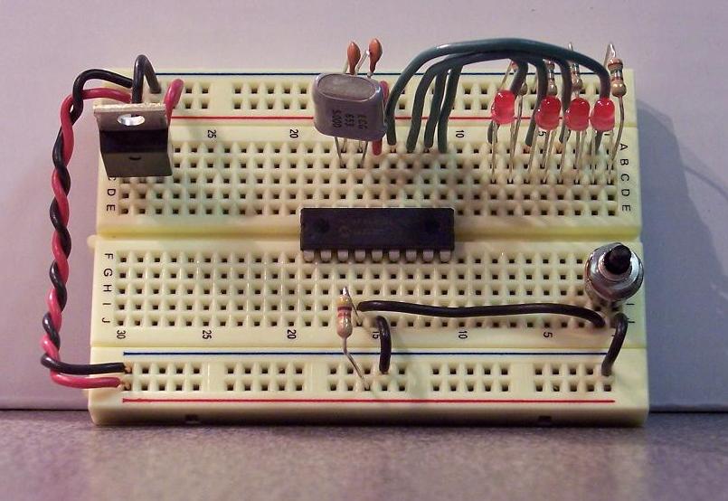
Here is my schematic for a test circuit with the PIC16F84A:
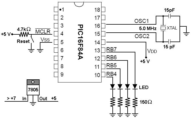
|
Here is a photo of the actual circuit. This image has balloon hot-spots.
Here is the assembly code. The goal of this program is to flash
the numbers 0 to 15 in binary on the LEDs.
Here is a copy of the
MPLAB IDE project files.
|