GPS & WD-C2401P
Jan 16, 2011
GPS and WD-C2401P
Last week, I thought I would learn how to make electronics aware of their location.
So, I figured I would make a GPS enabled device. The following are my notes.
| |
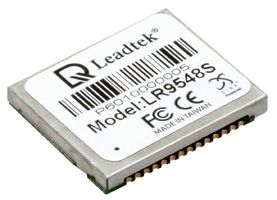
I searched Newark for a GPS chip. I decided on the LEADTEK - LR9548S - GPS RECEIVER MODULE . Unfortunately, all these chips are Surface Mount Devices (SMD). I was dreading the day that I had to begin working with SMD chips, but I decided I would give it a try. I probably should not have chosen a $60 chip for my first SMD experiment. The pins are 0.356 mm apart! And, they are nestled under the metal cover. That is insane! More on this later.
|
|
|
|
click to enlarge/reduce

click to enlarge/reduce
|
|
I needed to display the output from the chip to verify whether it worked. I hooked up a PIC18F4620 chip and programmed it with the standard LCD code. I had an untested LCD display from allelectronics.com. The display had 14 pins on the back. I could not find any connectors that would fit the pins. I decided to bend the pins over and to solder some wire to the pins. I connected the wires to a generic circuit board to form a connector.
|
|
I tested this display with the PIC LCD code and determined the code was incompatible. The display was marked as WD-C401P. I Googled this marking and found a web page discussing this display. It apparently conforms to the Hitachi HD66717 standard. I was astonished when I read that the author had also failed to find a suitable connector and bent the pins just as I did. With this page, I was able to develop the code to communicate with the display.
I did loose a couple of hours debugging the code. I don't know why, but sometimes I have to use the LAT reference for port pins instead of the PORT reference. For example, PORTBbits.RB4 versus LATBbits.LATB4. I could not get my data pins to transfer the data until I used the LAT reference for the pins. The code I used to communicate with this display is referenced at the bottom of this page.
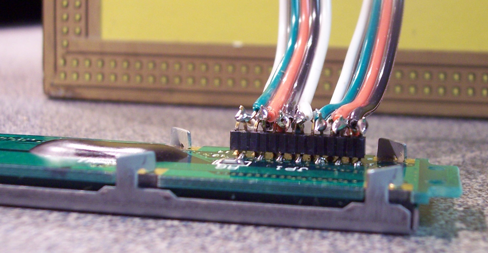
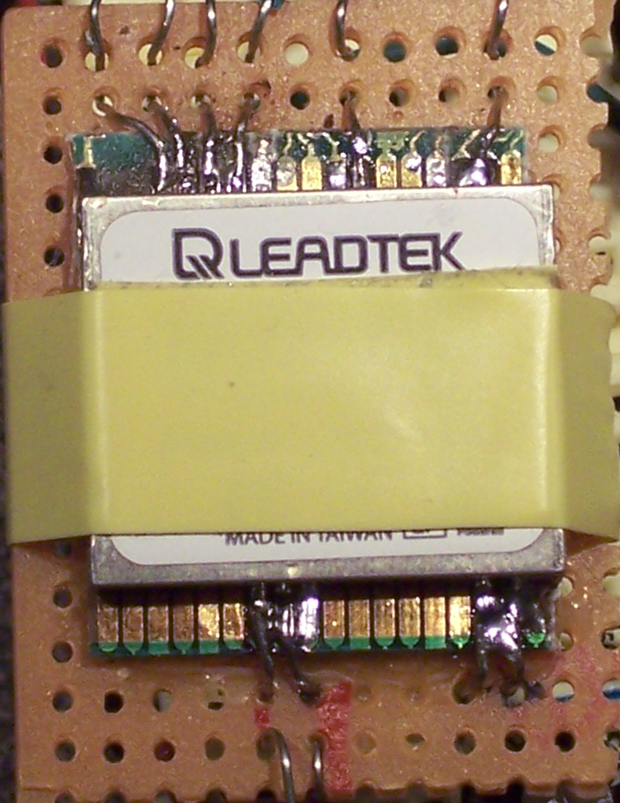
After shipping delays due to snow, the GPS chip arrived on a Friday after noon. I spent a while just looking at the chip deciding how to begin the assembly. I broke the metal contacts off of some network cards to serve as the pads onto which I would solder the chip. I glued these to a generic circuit board. I taped the chip to this board and began to solder the contacts. I added a wire to each contact for connecting with my controller. It took a few hours to solder just 12 connections. Most of this time was spent cleaning out the solder from the 0.356 mm space between the pins.
UPDATE: I found a good video on how to solder SMD chips from CuriousInventor.com. Apparently the trick is to use a lot of flux and a very small tip soldering iron.
UPDATE: Wow! Flux is awesome! Flux makes the solder wick work wonderfully. I was able to undo a solder joint and make a new one in just a couple of minutes, and it worked the first time. I think I might be ready for a nice soldering iron.
click to enlarge/reduce
| |
The datasheet indicates it will work on 3.3 to 5 Volts. So, I used a 5 Volt supply. I checked the serial outputs with the oscilloscope and saw nothing. I did some tests and found that pin 17 was connected to pin 16 with a small dab of solder. Pin 16 is connected to the 5 Volt power source. Pin 17 is described as "BOOTSEL: Pull high for programming mode. If not used, keep floating." I was afraid I had ruined the chip. I spent about 45 minutes removing the solder between these two pins. After cleaning this spot, I saw some data going to the wires.
I have got to learn how to properly mount SMD chips.
|
|
click to enlarge/reduce
|
I hooked the RX and TX to the PIC chip. After enabling the USART, nothing happened.
I spent hours reading over the datasheet and testing pieces of code.
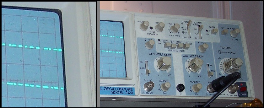
While looking at the oscilloscope, I realized the serial output voltage of the GPS chip was around 3 Volts.
The chip can operate from a 5 Volt source, but an internal voltage regulator reduces the voltage to around 2.9 Volts.
I used a couple of NPN transistors to translate this to a 5 Volt signal. (Actually, I used an N-MOSFET and an NPN BJT.)
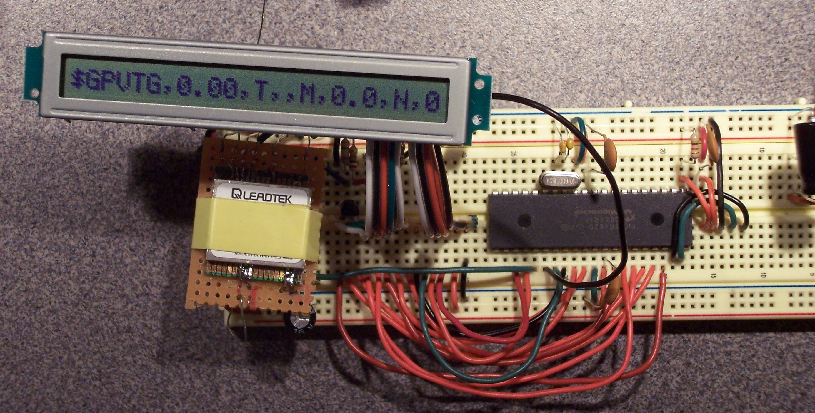
This did the trick. Here is a photo of the final setup.
I'm not sure what the output means, but that is next on my list. (NMEA)
click to enlarge/reduce
I used the iPhone to determine my GPS coordinates: 36.008059, 80.284983.
Google converted my address to almost the same values.
However, my new device displayed a $GPGGA sentence
that indicated my coordinates were 3600.4881, 8017.0923.
I assumed all I should do is move the decimal over.
Thus, I obtained 36.004881,80.170923. But, this is almost 10 miles away from where I live!
I could not understand how I had so much error. I played with the antenna, but the results were the same.
I did some searching and realized that the value 8017.0923 actually means 80 "degrees" and 17.0923 "minutes".
I divided the "minutes" by 60 to convert to a fraction of a degree.
| 8017.0923 | => | 80 + (17.0923/60) | = | 80.28487167 |
| 3600.4881 | => | 36 + (00.4881/60) | = | 36.008135 |
I put these values into google and it correctly found my location.
I hope these notes may be of help to someone else.
Here is an early version of my code as a tar file and as C files.
|


