| Disclaimer:The following are my notes. As I am learning electronics, I am making my notes available. I hope they will be of benefit. However, I do not guarantee the accuracy of my work. I recommend the reader exercise critical thinking.
|
Ethernet
The following are my notes from my work with Ethernet and the PIC Microcontroller.
SPI
I began playing with the Serial Peripheral Interface Bus (SPI) features of the PIC18F4550.
I successfully interfaced this chip with an SD Card using SPI.
I then learned about other chips that communicate via the SPI bus.
The ENC28J60 from Microchip is an Ethernet controller that communicates using the SPI bus.
So, I decided to make an Ethernet device.
These pages are my notes on how to create an Ethernet/TCPIP web server
that gives the current temperature.
TQFP
Microchip produces the PIC18F97J60 chip that has a built-in Ethernet controller.
But, my little programmer will not work with this chip since this chip is
packaged as a Quad Flat Pack (TQFP).
The programmers for this chip cost a few hundred to over a thousand dollars.
So, I attempted this endeavor with my current tools.
ENC28J60
I purchased a couple of the ENC28J60 chips. The datasheet is just under 100 pages.
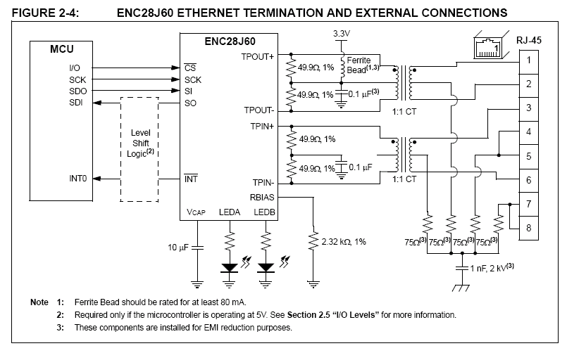
The overview section says "two pulse
transformers and a few passive components are all that
are required to connect a microcontroller to an Ethernet
network." Section 2 discusses these external connections in detail.
I needed a 25 MHz oscillator, a pulse transformer, some very precise resistors and some high voltage capacitors. Radio Shack does sell some 1% tolerance resistors.
I did not discover those until I had already purchased some 2% tolerance resistors from another store. I still don't know where to by the appropriate capacitor.
I could not find the pulse transformer for sale on the Internet.
Then I realized that I already had a few of them.
I cannibalized an old Ethernet card for a Pulse 1012 and a 25 MHz oscillator.
Later, I found the transformers for sale from
www.pca.com. They cost 3 to 5 dollars when purchasing a few of them.
The figure 2-4 from datasheet provides a good starting point.
The datasheet specifies this chip should operate a 3.3 volts.
I used an LM317 to generate this source.
Since the PIC18F chip utilized 5 volts, I wondered if I needed to step-down
the voltage for SPI communication. Then I read the following from the
datasheet, "The ENC28J60 is a 3.3V part; however, it was
designed to be easily integrated into 5V systems. The
SPI CS, SCK and SI inputs, as well as the RESET pin,
are all 5V tolerant."
click to enlarge/reduce
I was able to build an Ethernet device that interfaced with the PIC18F4550 chip.
I downloaded the libraries and instructions from Microchip's Ethernet design center.
However, I was only able to include ARP, IP and ICMP within the 32 KB
of program memory. However, I was able to make a device with a static IP number, and
I could ping the device from my Linux computer.
This provided good positive reinforcement, but is was not very fun.
Due to the memory constraints, I started looking for a bigger chip.
PIC18F4620
The PIC18F4620 supports SPI, holds 64 KB of programming and works
with my programmer. The oscillator configuration and SPI pins are a
little different. I planned to use DHCP, so I need a way for the device
to indicate its IP address. I decided to make a display unit.
With all the new pices to the puzzle, I had to tackle them in two steps.
Step 1: Make a display unit and display the current temperature.
Step 2: Add the Ethernet hardware and the TCP/IP server code.
|


