| Disclaimer:The following are my notes. As I am learning electronics, I am making my notes available. I hope they will be of benefit. However, I do not guarantee the accuracy of my work. I recommend the reader exercise critical thinking.
|
Step 3
The following are my notes from my work with Ethernet and the PIC Microcontroller.
Step 3: Design a printed circuit board.
click to enlarge/reduce
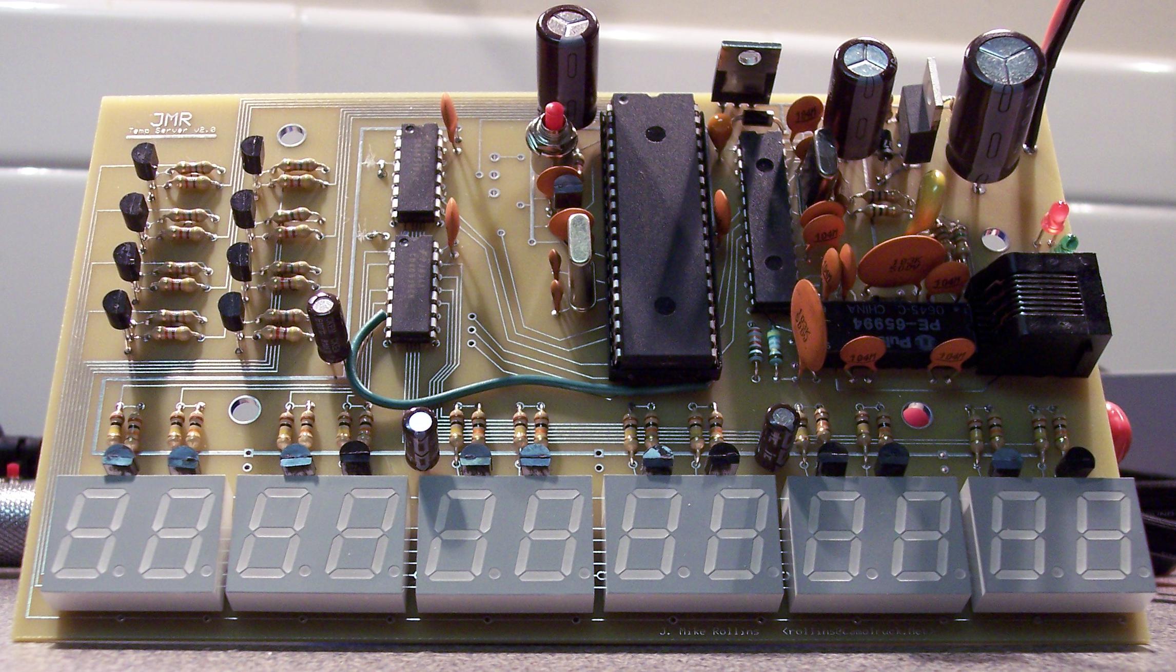
PCB
I designed a circuit board using the software from ExpressPCB. It cost about $100 to have two boards made. (The minimum order is 2.) As I was building on the first board, I found a few errors. I then built on the second board and it worked.
I purchased the recommended components such as a 2kv 1nF capacitor, some 49.9 Ohm 1% resistors and a new Pulse transformer. I had to update my design to accommodate the new transformer.
I extended the display to incorporate 12 units. The display cycles through the IP address, the MAC address and the current temperature. It acquires an IP address via DHCP. I can power it with a 9V battery... for a few minutes. I've also powered it from a small Solar Panel.
|


