| Disclaimer:The following are my notes. As I am learning electronics, I am making my notes available. I hope they will be of benefit. However, I do not guarantee the accuracy of my work. I recommend the reader exercise critical thinking.
|
SMP with 317
LM317 and a Switching Power Supply
I was researching methods for charging batteries when I began to debate whether to use
a switching power supply versus a linear regulator.
While reading the datasheet for the LM317 regulator, I discovered you can make a switching power supply using this regulator. (See the "Typical Applications" section of the datasheet.)
In the past, I used pulse width modulation to implement switching power supplies. I did this
with a 555 chip and a PIC18F chip. However, this LM317 schematic had no pulse width generator!
It seem to operate on feedback alone.
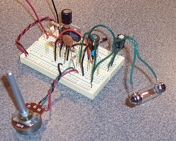
I had to see if this really worked. I built a close approximation of the schematic
in the datasheet. It worked indeed!
click to enlarge/reduce
My next question was whether this was more efficient than a linear regulator.
I compared this switching regulator to a simple 7805 regulator.
In both tests, I used a power supply of 16 volts capable of 3 amps.
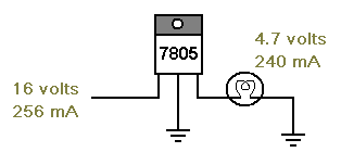
Test 1: LM7805
I connected a 7805 regulator to the 16 volt power source and used this to power a light bulb.
I observed 240 mAmps of current going through the bulb at 4.7 volts.
This yields 1.1 Watts. I measured the current supplied to the regulator to be 256 mAmps at 16 volts.
This is 4.1 Watts.
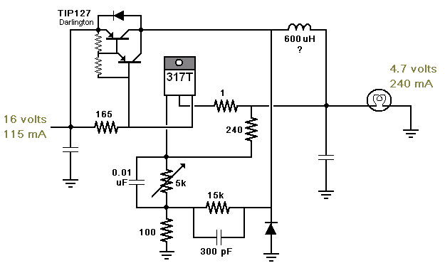
Test 2: LM317 and Switching Circuit
I connected the new LM317 circuit to same 16 volt power source and used this to power
the same light bulb.
I adjusted the voltage until I saw a 4.7 volt drop across the light bulb.
At this point, I found the current through the bulb to be 243 mAmps. This is again 1.1 Watts.
The current flowing into the circuit was 115 mAmps at 16 volts! This is 1.8 Watts!
This is less than 1/2 the power used by the 7805.
Conclusion
This is my favorite circuit for this week.
I still don't know why it works... but I like it!
Notes
I tested this with a single transistor such as a 2N3906 and a protection diode.
The current drain was over 200 mA.
I then built a Darlington out of two transistors, a couple of resistors and a diode.
The current was back down around 115 mA.
I suspect the pulses are weak without the sensitivity of the Darlington.
I tried to make a similar switched power supply using just a voltage comparator. It worked.
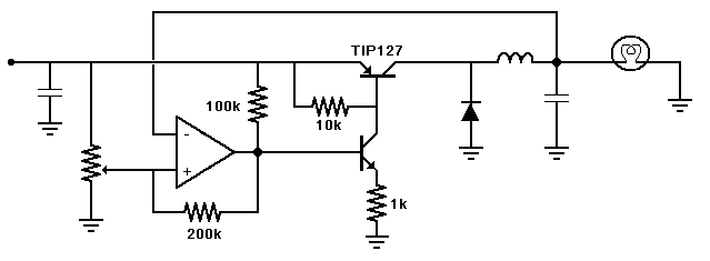
|


