Power Supply
Dec 28, 2009
Last year, I made a power supply with multiple power outputs. Today, I had to do some internal maintenance, so
I figured I would write a web page documenting this project.
I wanted a power supply that offered +5V and +12V. These are standard for many of my projects. I also wanted some higher voltage outputs. I started with a fuse and a 24 Volt, center tapped transformer. This provides +12 Volts and +24 Volts AC. After rectification, this is about +16 Volts and +32 Volts.
The first output on my power supply is Ground. Next, I have the +16 and +32 un-regulated DC outputs.
I use a 7809 and a 7812 regulator to provide +5 and +12.
click to enlarge/reduce
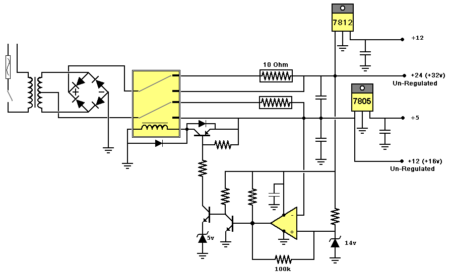
I wanted to limit the inrush current of the system. It turns out, that this same current limiting circuit
also protects in the event of a short circuit. After rectification, the current is initially
sent through a huge 10 Ohm resistor and then to a capacitor. The circuit observes the capacitor voltage.
A voltage comparator checks this voltage with the voltage drop across a 14 Volt Zener Diode.
(UPDATE: The Schmitt Trigger on the comparator is useless in this schematic.)
When the observed Voltage is higher than the 14 Volt Zener, a relay bypasses the 10 Ohm resistor.
This circuit stays active. If the capacitor voltage were to drop below the 14 Volt reference, then the
relay sends the current back through the 10 Ohm resistor. I have not blown the 3 Amp fuse yet.
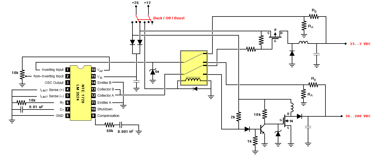
Next, I use an LM3524 in Buck and Boost mode. I use a single IC for both modes.
A relay switches the inputs and outputs for each mode. These provide outputs ranging
from around 7 Volts to 200 Volts. I used a STW18NB40 for my Boosting circuit, so I should be able to
obtain up to 400 volts, but my capacitor is only rated for 200 Volts. Furthermore, 200 Volts is
plenty.
click to enlarge/reduce
|
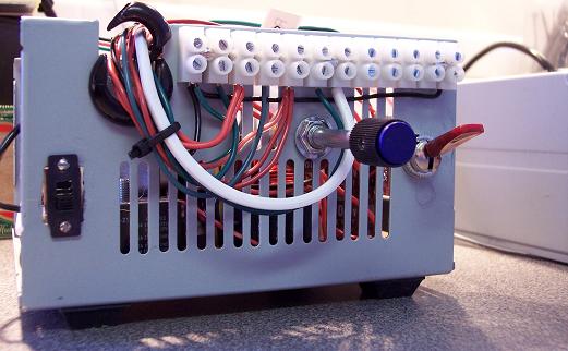
I love computer power supplies. They provide a nice supply of capacitors, inductors and fans. The metal
case is an excellent project enclosure. Here is the front of my setup. There is an off/on switch, a Buck/Boost switch and a variable voltage potentiometer. Along the top are the various power outputs.
|
click to enlarge/reduce
|
click to enlarge/reduce
|
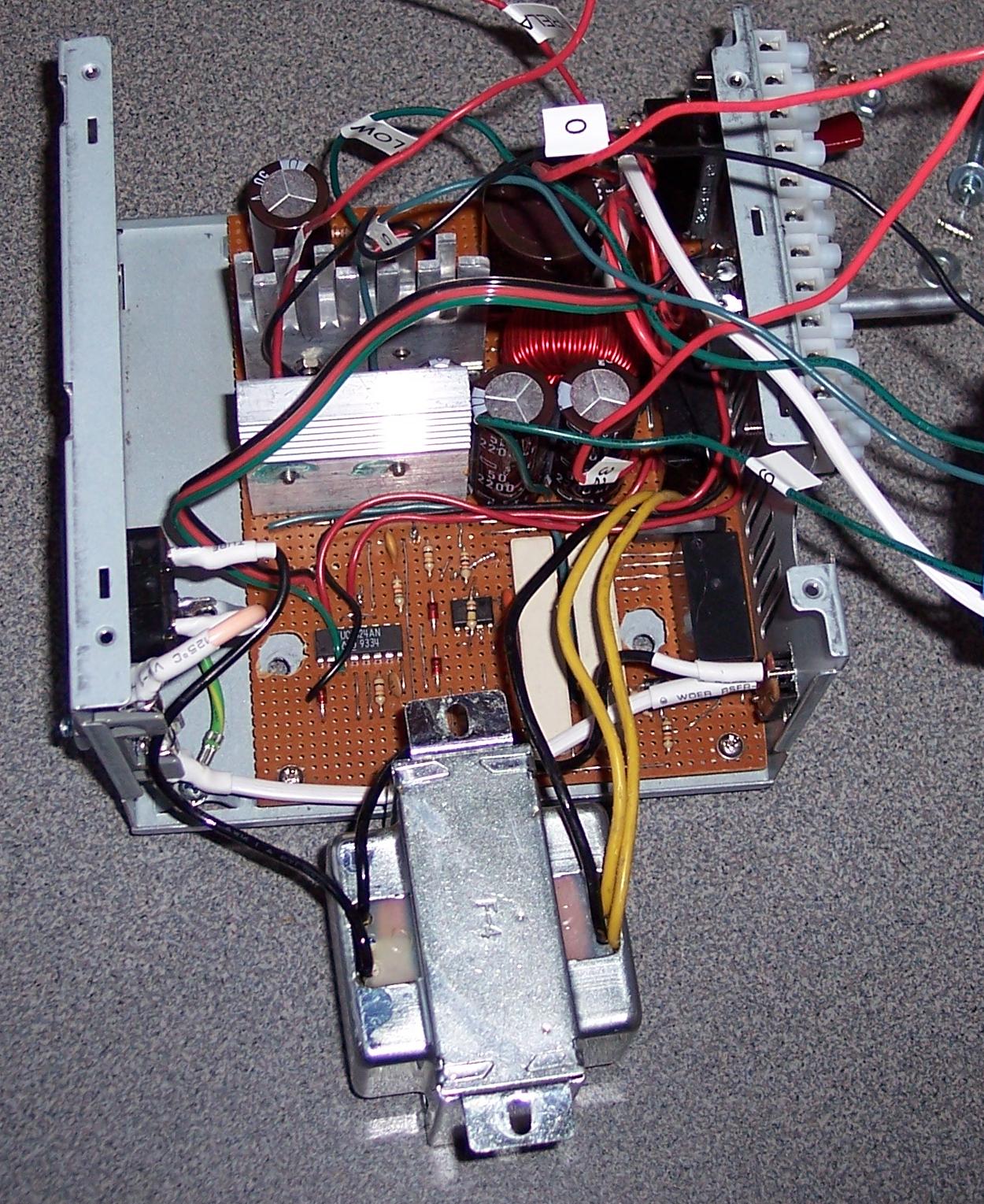
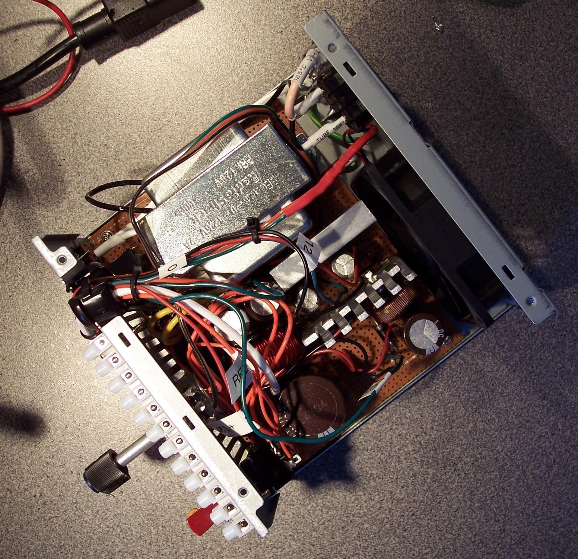
I needed to think in three dimensions to fit all of
my circuitry into this enclosure. The transformer sits on metal spacers. Under the transformer resides
the low profile circuitry. This includes the LM3524, the big resistors and the voltage comparator. The relays, inductors and large capacitors sit in the open area.
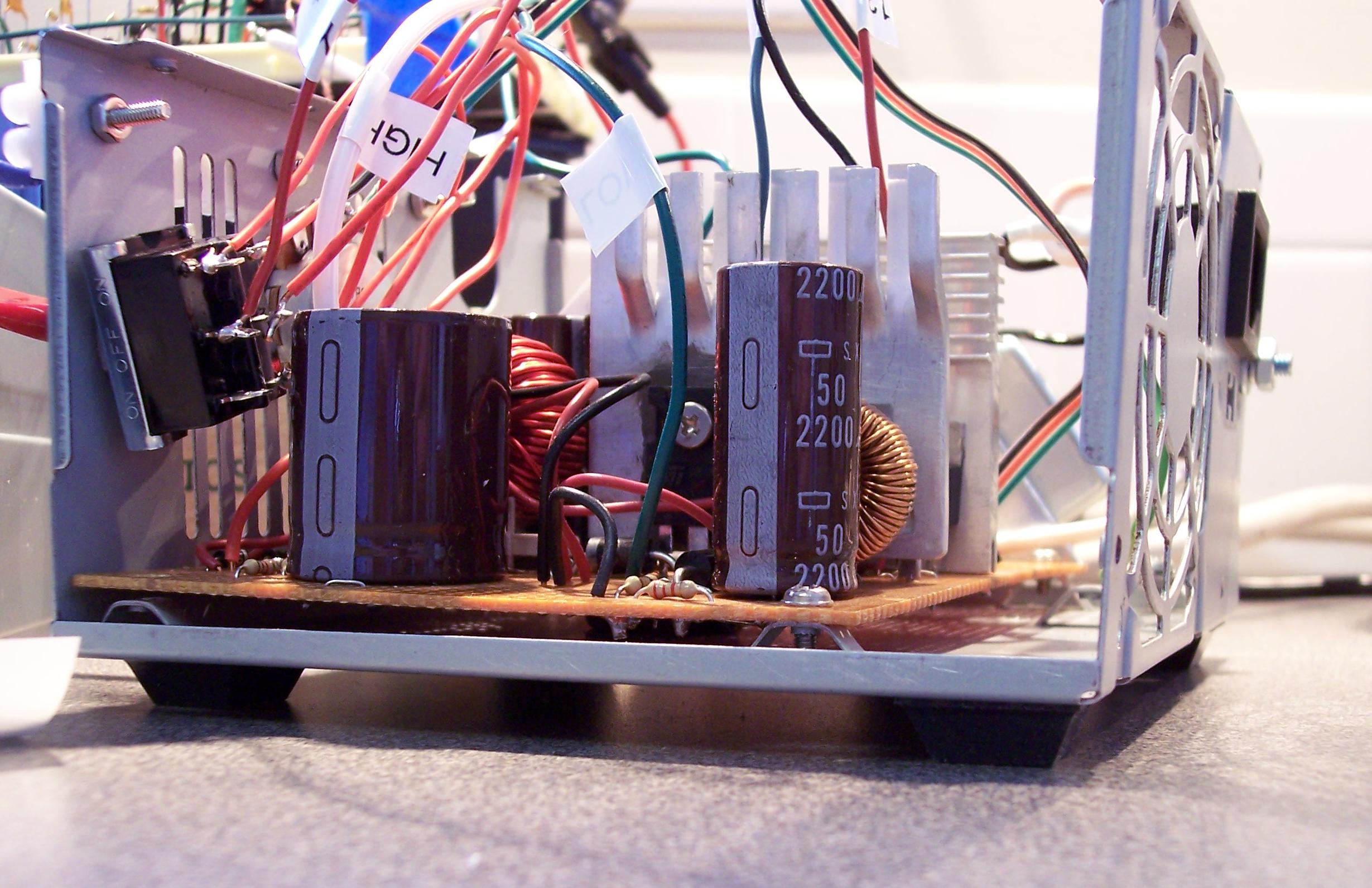
In the upper part of this photo are the capacitors and inductors for the Buck and Boost circuits.
In the middle of this photo are two heat sinks cannibalized from another computer power supply. On these
heat sinks are mounted the LM7805, LM7812, a N-Channel MOSFET and an P-Channel MOSFET.
The bottom part of this photo show the low profile components that sit under the transformer.
|
|
Below, is a photo of the Buck and Boost switching components. I don't yet have a good idea for
selecting the right inductor for the application. These work, but they may be horribly inefficient.
To the right, you can see the switch to select the Buck/Boost mode and the potentiometer used
to dial in the desired voltage. The fan is also included in this photo.
click to enlarge/reduce
|
click to enlarge/reduce
|
Notes:
Jan 7, 2010: I keep blowing the diode on the boost circuit when I select a voltage of around 130 Volts.
I originally used a 1N5401 for rated for 3A and 100V. I have no doubt why this one failed.
I replaced it with a 1N5406 rated for 3A and 600V. This one also failed. I now have a 1N5399
rated at 1.5A and 1000V. We will see how long this one last.
I'm not sure whether it is the voltage or the current that is killing the diodes.
Feb 28, 2010: I set the power setting to about 180 Volts and tested a circuit I was building. I let it run for about a minute and I heard a pop from inside the power supply. Not only did the high voltage system not work, but even the 12 volt would not operate! The relay would activate and the 10 Ohm resistors would get insanely hot. I found a wire that should read about 24 volts to be at only 5 volts.
I disconnected and tested the transformer. It was good, and the rectifier was good too.
I found the following to be faulty:
Two NPN transistors, the 7805 regulator, the high voltage diode and the 3524 chip. (I mistakenly had the 7805 hooked to the 24 volt system.)
I believe the high voltage diode failed allowing the 180 volts stored the capacitor to flow back through the inductor to all the components hooked to the 24 volt unregulated supply. A few of the devices failed, and one finally shorted out and prevented the remaining devices from failing.
I seated the 3524 chip into a socket so I can swap it out easily in the future. I also put in a 3 Amp/1000V diode. This setup with all the wires and such is getting difficult to maintain. I think it is about time to design a nice PCB for this project. And, I probably should learn more about voltage clamps. I'm thinking I would like to add a voltage meter and current meter too. If I used a PIC microcontroller, I could also use temperature sensor to prevent overheating. Hmmm....
|


