| Disclaimer:The following are my notes. As I am learning electronics, I am making my notes available. I hope they will be of benefit. However, I do not guarantee the accuracy of my work. I recommend the reader exercise critical thinking.
|
Simulator: Zener
Zener Diode Simulator
I found the Java applet circuit simulator program written by Paul Falstad
to be of significant value while learning electronics. I continue to
be amazed at the accuracy of the program. As a computer person, I could
not resist the urge to see how the program worked. The following
are my notes from this exploration.
The simulator program did not include a Zener diode. As my little project,
I attempted to add a Zener diode to the application.
Falstad currently includeds my Zener code into the main source.
While reading through the code, I noticed references to the book
Electronic Circuit & System Simulation Methods.
This book is for serious readers only. This is a very good book,
but you need a good foundation in numerical analysis.
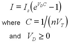
One of the first examples in the book is about the Diode. The book
references the "Shockley diode equation".
The diode wikipedia page
discusses this equation. I found that the simulator program uses
this equation too.
- Is is the reverse bias saturation current
- Vd is the voltage difference
- Vt is the thermal voltage
- n is the emission coefficient, also known as the ideality factor
- C is the "voltage coefficient"
|
 |
I needed a Zener Diode equation. I could not find one quickly, so I made
up my own. I decided to simulate the Zener breakdown region in the same
manner as the forward bias region.
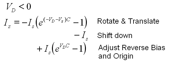
For my equation, I rotate the Shockley equation 180 degrees. Through a
horizontal translation, I place the exponential curve at the Zener voltage.
For a regular diode in reverse bias mode, a little current leaks.
This is called the reverse bias saturation current and is denoted
as Is in the equations. I had to compensate for the reverse
bias properties. I did this by subtracting the Is and adding the
original Shockley diode equation. This gave me the desired behavior in
the reverse bias mode and at the origin.
I later learned of
a web site
with some equations for the Zener diode. I believe the only difference in my equations
is that I included a little offset in the x-axis. I did a physical experiment
with an 1N4733A 5.1V Zener and concluded the simulation was better without my offset.
So, I updated my equations.
class ZenerElm extends CircuitElm
I added a class called ZenerElm that derives from CircuitElm.
This class started as a copy of the DiodeElm.
I made some modifications in the setup function.
Based on information from various web sites, I assigned 0.02585 for the value of Vt, the "Thermal Voltage".
Thus the vdcoef (voltage difference coefficient) would be 1/vt. I added a data member
to store the Zener voltage. It defaults to 5.0, double zvoltage = 5.0.
I found diode data sheets showing about 5 to 10 uAmps for the reverse
bias current leakage value. I updated the leakage value as
final double leakage = 5e-6.
I updated the constructors to support the import and export of the Zener data. I added
a flag for Vz, static final int FLAG_ZVOLTAGE = 2 and added a string
tokenizer statement. I updated the functions getDumpType()
and dump() as well.
void calculateCurrent()
I added the Zener equation to this function. It tests for positive or
negative voltage differences. If the voltage difference is zero or
positive, the behavior is that of the regular diode class.
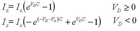
If the voltage difference is negative, it calculates the following:
current = -leakage*
            (
                Math.exp(voltdiff*vdcoef)
                - Math.exp((-voltdiff-zvoltage)*vdcoef)
                - 1
            );
Here are the actual equations:
void doStep()
I'm still on Chapter 1 of the book. But, it seems the basic idea of the simulator
is to translate the circuit into an equation in terms of Vd. Then an iterative
process attempts to determine the best value for Vd that solves the equation.
The book discuses the Newton-Raphson process to solve the equation.
The doStep() function is part of this iterative process.
Let's say f(v) is our diode equation and Vd is the voltage drop being tested.
The value of geq is the derivative of the diode equation evaluated at Vd, f'(Vd). The value for nc is f(Vd) + f'(Vd)*Vd.
I see similarities and differences in this last equation and the Newton-Raphson
method, f'(v+dv)=f(v)+f'(v)*dv. But, I don't really understand what it does.
(I am still on Chapter 1 of the book.)
double limitStep(double vnew, double vold)
I don't understand this Java function. This is covered in Chapter 10,
"Damped Newton-Raphson Iteration". As I understand, this is intended to keep
the iterative process from spiraling out-of-control. I found this function to be
very important.
My equation for the reverse bias region is basically the "Shockley diode equation"
with translated coordinates. So, I decided to use
original code for the diode but with translated voltage values.
vnew = -vnew - zvoltage;
vold = -vold - zvoltage;
... original diode logic ...
vnew = -(vnew+zvoltage);
Aesthetics
Since the original diode only worked in one direction, the reverse bias
region of displayed the current traveling in the opposite direction.
This was rather entertaining. To resolve this, I copied the
doDots() function from the base class and extended it to
operate the dots in reverse.
Other modification include updating the getInfo() to display
the Vz value, adding the Zener icon and updating getEditInfo()
to allow the user to assign the Zener voltage.
|


