BLDC
Sep 11, 2010
Disclaimer: These are my notes from my experiments with making a controller for a three phase dc hub motor. I do not imply my notes to be accurate nor do I imply that experimentation is safe.
Brushless DC
I took on the challenge to test a friend's Three-Phase
Brushless DC
Hub motor with
Hall effect sensors.
I knew almost nothing about this type of motor, and I was not sure that this particular motor worked.
I had a couple of controllers to test but could get neither to work. So, I turned to the Internet. I found a
few documents explaining how these controllers and motors operate.
This Zilog document
explains the concepts very well and provides schematics of a controller using a Z8FMC1500 chip.
However, google doesn't seem to know anything about that chip.
The motor has three wires to activate the three sets of coils.
At any time, one wire is connected to the voltage source, one is connected to ground and
one is connected to nothing (open).
The six combinations must occur in a particular order for the motor to operate smoothly.
The motor contains three
Hall effect sensors
that detect a magnetic field and produces an electrical signal in response.
As the motor turns, the controller observes six unique Hall sensor outputs.
Using the Hall sensors, the controller determines which coils it should activate to keep the motor turning.
Five additional wires are needed for the Hall sensors: A positive, a ground and one wire for each sensor.
The motor will function only if the Hall sensors and motor drive wires are connected correctly.
There are 36 possible combinations to connect the six wires. I suspect there is some symmetry
that will reduce the number of combinations you must try, but I recommend making a list of all
the combinations and working through them. Many combinations will cause the motor to jerk, buzz or grind.
You will know when you hit on a workable combination. You should find one combination that spins the
motor forward and one that spins it in reverse.
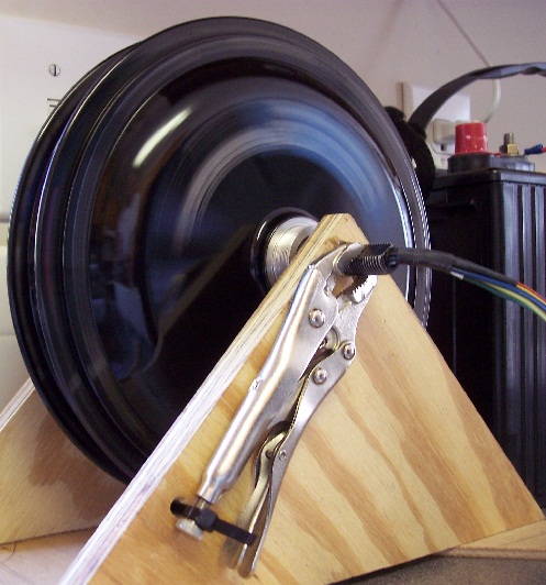
| Move the mouse in the image to view the components. |
It's Spinning! |
|
|
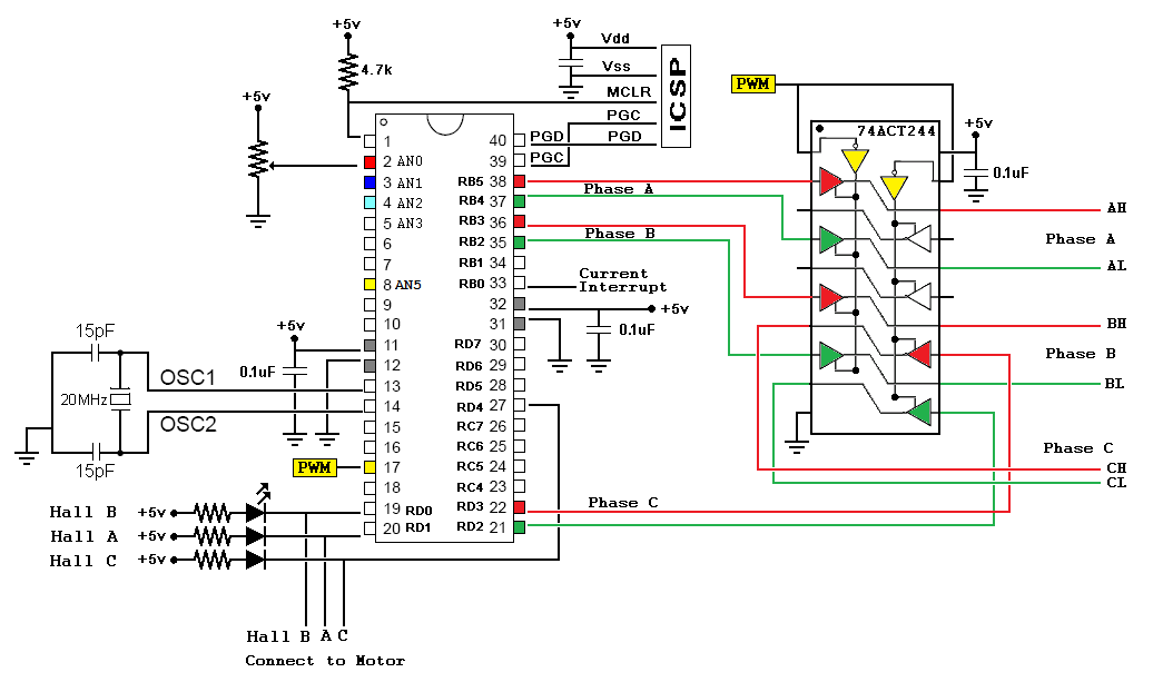
Microcontroller
I used a PIC18F4550 for this project just because I had some available.
The PIC18F4431
is a better choice.
Microchip provides a document
detailing how to use this chip to drive a three phase BLDC motor using this chip.
Additionally, there are chips such as UC3625 that are designed specifically for this purpose.
The hall sensors connect to digital input pin on the chip.
A resistor connected to +5 Volts is also connected to this pin. When the sensor activates, it pulls the resistor to ground. The best configuration would be to connect the three sensors to interrupt pins; however, I needed one of the interrupt pins for the current limiting feature. My system will poll the digital inputs.
I use the PICKit3 to program the chip. Here is a link to the firmware code the implements a simple PWM motor control. Disclaimer: I do not guarantee that this code will work, nor do I imply that experimentation is safe.
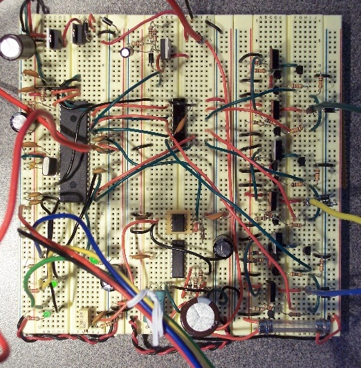
Driver Stage
Each of the three coil wires will need to drive a positive current and a negative current.
I used a PNP/NPN push-pull
transistor output configuration. This means I have six power transistors that are controlled using
six pins from the Microcontroller. A few additional transistors serve as the driver for the power transistors.
click to enlarge/reduce
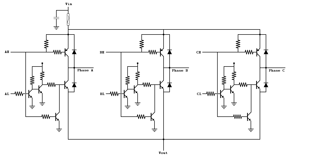 When using transistors in a push-pull configuration, a fatal flaw occurs when both transistors are active
at the same time. This causes a short circuit between the transistors. I added an additional transistor
to prevent this from occurring.
When using transistors in a push-pull configuration, a fatal flaw occurs when both transistors are active
at the same time. This causes a short circuit between the transistors. I added an additional transistor
to prevent this from occurring.
Pulse Width Modulation
Six wires carry the drive signal to the power transistors. In between the microcontroller and driver circuits, the six wires connect into a 74ACT244 buffer chip. This chip
will repeat what the input signals to output signals.
Two additional pins on the 74ACT244 chip will cause all output signals to be null.
The Microcontroller's Pulse Width Modulation
signal feeds these two pins resulting in the PWM signal imposed on the drive signals.
The PIC18F4431 chip would
provide six PWM output pins and would eliminate the need for this buffer. This will be my next design.
click to enlarge/reduce
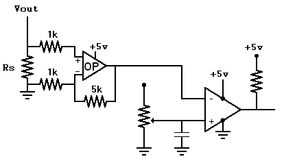
Current Limiting
The current limiting feature will end the current pulse if the current is over a preset value.
I placed a small resistor in between the power transistors and ground.
An op amp amplifies the voltage drop across this resistor and provides this voltage to a comparator.
The comparator checks this voltage against a preset reference.
If the voltage is greater than our reference, an interrupt is sent to the Microcontroller.
My implementation seemed to work.
In a production device, I would use a faster and more precise op amp and a faster comparator.
Feedback
My first design used a potentiometer to select the pulse width.
This is an open-loop system with no feedback.
Thus, I could place my hand on the motor and easy slow it down.
A better method is to use the potentiometer to select the desired spinning rate of the motor.
Then, the microcontroller compares this selected rate to the actual rate and adjusts the pulse width accordingly.
A general method for this is called the Proportional-Integral-Derivative Controller (PID controller). The following graph shows a simulation of the PID feedback I used in this system.
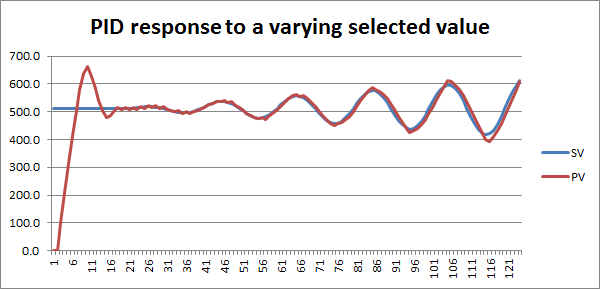
With this feedback loop, when I place my hand on the motor, I can feel it increasing torque (the pulse width) to maintain the selected speed.
I did not use the derivative factor. So, I actually had a PI Loop.
The integral term is intended to have a "memory" of the previous errors.
The algorithm requires that the system overshoot the target value to nullify this accumulated error.
This is a problem when the selected value is the maximum possible value.
Since the system cannot overshoot this value, the error will never go away.
I wanted to dampen this effect.
Instead of adding the current error to the sum of the past error, I added the current error to 80% of the past error.
Here is an Excel file that illustrates the feedback loop.
Future
My next design will use the PIC18F4431 chip and will use MOSFETS.
|


