|
|
Function Gen
Jan 23, 2009
|
I've been studying switching power supplies, inductors and transformers.
Unfortunately, standard multimeters do not measure inductors.
I used a little breadboard circuit to generate a sine wave so I could measure inductance
as this page demonstrates
I wanted a more permanent method for generating sine waves of various frequencies.
So, over the past week, I made a function generator.
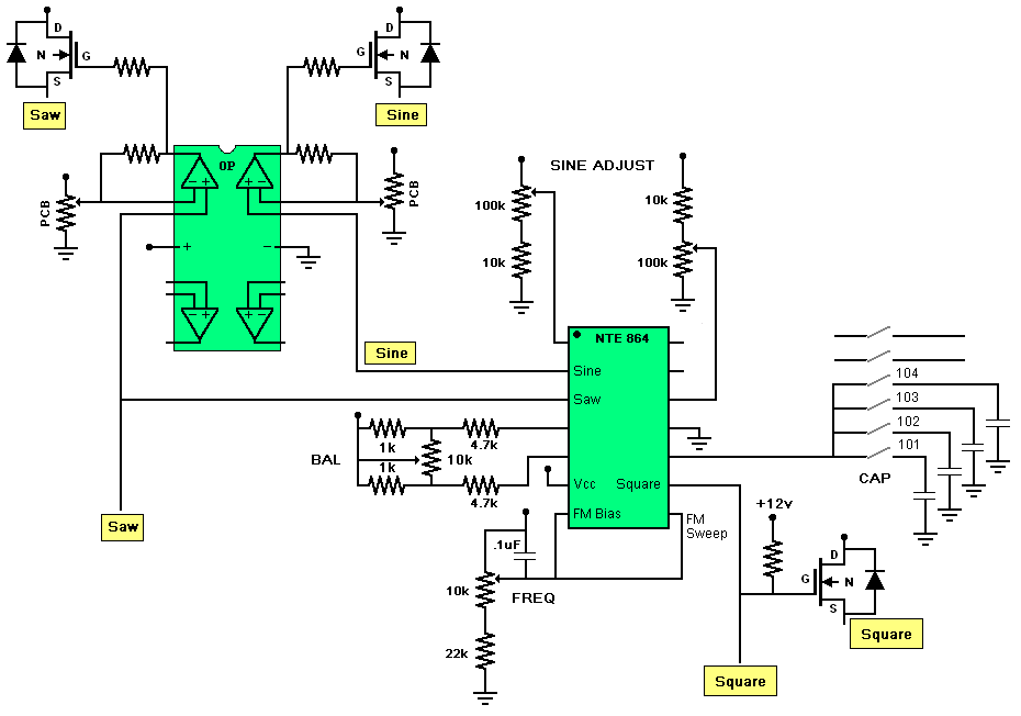
I started with an NTE864 chip.
The ICL8038 data sheet provides examples
I could apply to the NTE864.
A timing capacitor and a resistor set the frequency. Three output pins provide a square wave,
a sine wave and a sawtooth wave.
Other resistors and potentiometers fine tune the shape of the wave.
The multitude of potentiometers becomes messy on a breadboard.
This is the reason I wanted a more permanent solution.
|
click to enlarge/reduce
|
|
I used an op-amp to amplify the sine and sawtooth wave.
I used the Radio Shack LM324 quad op-amp since it would work within the 12 volt supply.
The sine, sawtooth and square signals are each sent to an IRF510 MOSFET to provide an ample supply of current for applications.
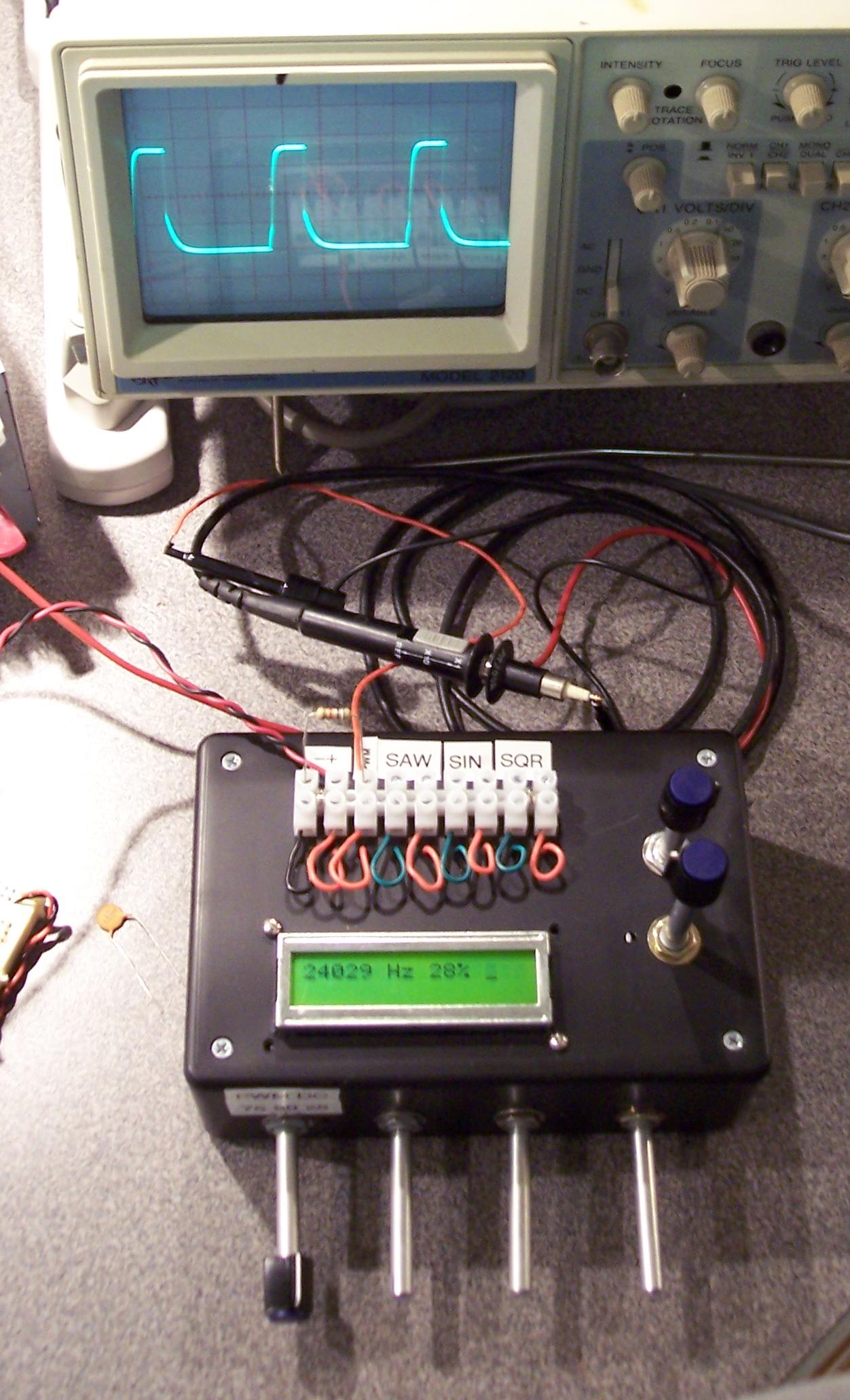
On the outside of the enclosure, I have outputs for the three wave forms from the NTE864
and for the three outputs from the MOSFETs.
Two potentiometers allow for sine wave adjustment, one potentiometer (POT) adjusts balance
and one POT adjusts the frequency.
To provide a wide range of frequencies, I used a selector switch from Radio Shack that lets
me select from a 104, 103, 102 and a 101 capacitor (0.1 uF - 0.0001 uF).
|
click to enlarge/reduce
|
|
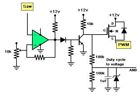
But, this still seemed a bit boring. I decided it would be nice to have a Pulse Width Modulation (PWM) output.
I used a voltage comparator to compare the voltage of the sawtooth wave with a voltage the user sets
with another POT. The output goes to a MOSFET to provide a power output. I also added a little filter
at the base of the MOSFET. This filter takes the PWM duty cycle and converts it into a voltage value.
A longer duty cycle will have a higher voltage.
|
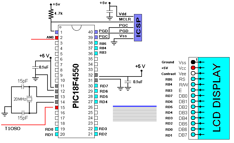
To really make the project interesting, I added a microcontroller and a display unit to
show the frequency and the duty cycle. With this display, I will not be tied to an oscilloscope.
I used a PIC18F4550 chip with a 20 MHz crystal.
This results in a clock speed of 48 MHz ((20MHz/5)->PLL->96MHz/2=48MHz).
I added an RJ45 port so I could use the In Circuit Serial Programming with the PIC Kit 3.
If I had understood the speed and convenience of the PIC Kit 3, I would have bought it a long time ago. It is much faster than the PIC Start Plus and the ICSP is extremely convenient when the chip is in a location not easy to access.
The display unit came from an old HP printer.
I used a section of an IDE cable to connect the display to the Microcontroller.
The display unit conforms to the Hitachi HD44780 LCD specifications.
A PIC18F driver for this display is readily available. However, I forgot that the microcontroller
code required that the pins of the display be within one port. So, I had to hack the display
code to support pins divided over multiple ports. (Not a pretty hack, but it works.)
|
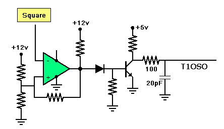
To determine the frequency, the square wave from the NTE864 is feed through a voltage comparator
and into the microcontroller's external Timer1 input.
Timer1 counts the number of "ticks" of the square wave. Timer0 serves as a real-time clock.
The basic algorithm is to calculate the ratio of Timer1/Timer0 when either Timer0 or Timer1 overflows.
The microcontroller also reads the voltage value from the PWM circuit, the AN0 output, to estimate the
duty cycle. Here is a link to the PIC18F4550 MPLAB C code.
|
|
|
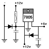
This unit operates from a +12 volt supply. A 7805 regulator provides power for the +5v system.
I added one new feature to make sure I would not destroy anything of value if I were to reverse the +/- inputs.
I added a diode from the - to the +. If I swap the + and -, it should blow a fuse before damaging anything.
However, I did not have room for a fuse in the enclosure.
So, it should blow the fuse in the power supply to this device.
|
click to enlarge/reduce
|
|
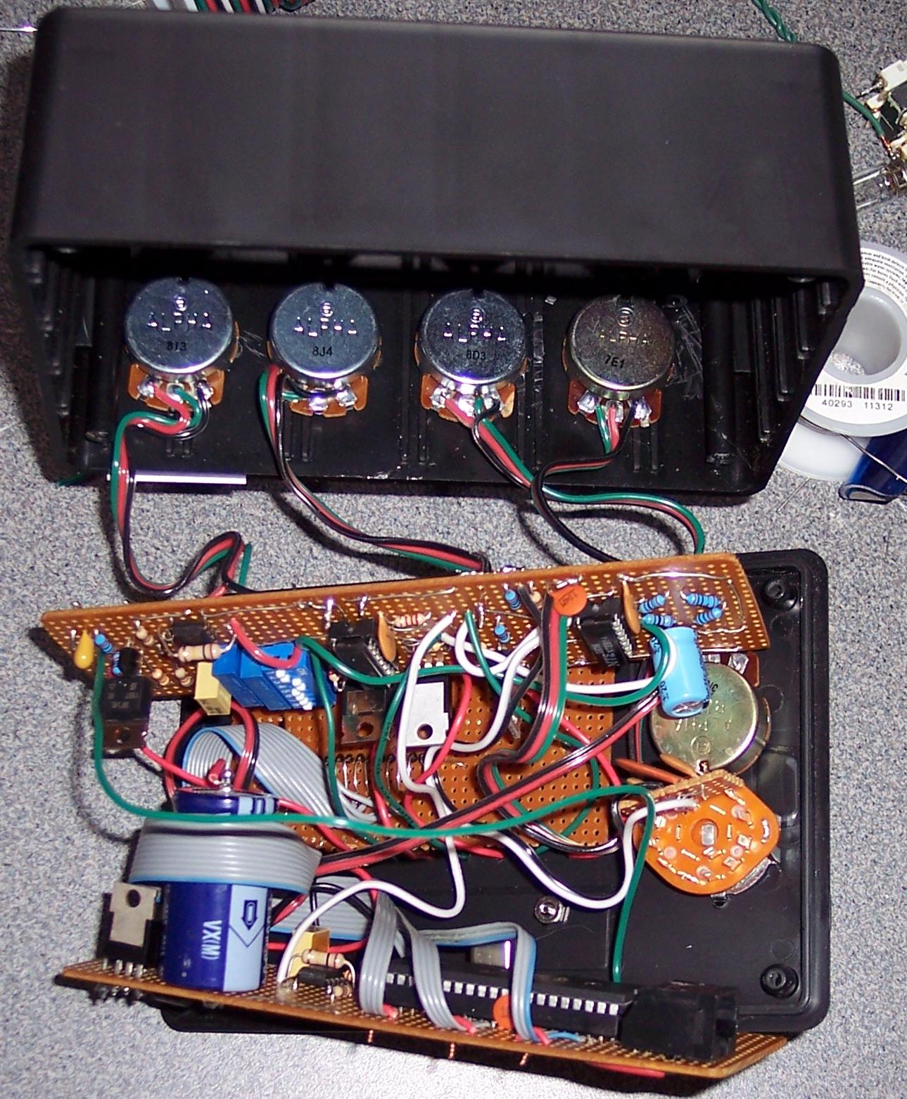
Here is a photo of the inside.
click to enlarge/reduce
|
|


