LM3524 Motor Control
|
I've contemplated making my own controller for my electric truck.
I've seen a few schematics and thought it was about time to experiment a little.
Today, I received a question via email about motor speed control, so I thought I would
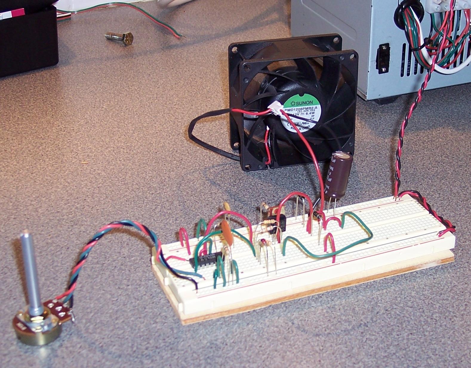
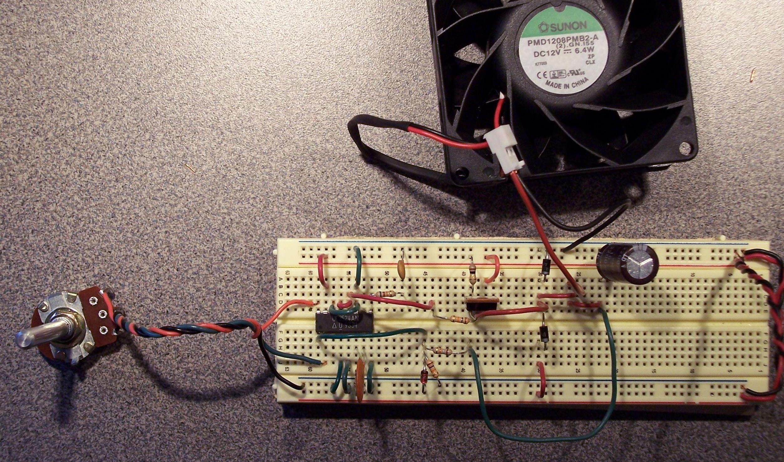
start my experiments with the speed control of a 12 volt fan.
|
click to enlarge/reduce
|
The LM3524 chip is common in switching power supplies. I've made one such power supply
that I use to generate 9 to 200 volts from a 24 volt dc supply. The LM3524 is a Pulse Width Modulation
control system that incorporates feedback to adjust the pulse width. This chip can be use in many
other applications.
I used a UC3524AN from Electronic Goldmine for my experiment.
When controlling a motor, the RPM of the motor is the best form of feedback. In my current test,
I do not have a way to determine the RPM of the motor. Instead, I feedback the voltage level of
the motor to the LM3524. This effectively produces a switching voltage regulator for the motor.
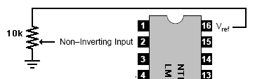
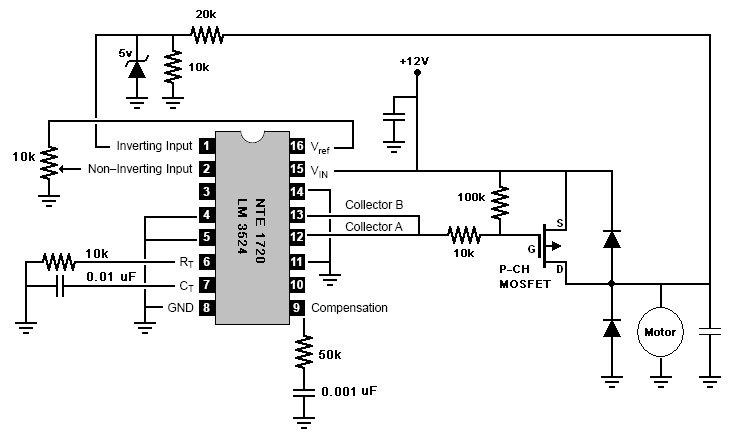
The 3524 uses a voltage value from 0 to 5 volts to determine the pulse width. The 3524 has an
internal 5 volt regulator that outputs on pin 16 (Vref). A potentiometer
connects to this pin and to ground. This potentiometer produces a variable voltage reference for pin 2.
This value will directly influence the pulse width.
|
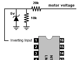
The 3524 monitors the voltage of pin 1 and adjusts the pulse width in an attempt to keep the voltage on
pin 1 the same as that set on pin 2. The voltage on the motor will be 0 to 12 volts. Since the 3524
requires a 5 volt scale, I use a voltage divider to scale the motor voltage in the range of 0 to 5 volts.
A 20k and 10k resistor performs this scale, and a 5 volt Zener clamp ensures that no more than 5 volts is given to pin 1.
|
 |
 |
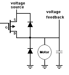
The driver is a P-Channel MOSFET. MOSFETs turn on and off abruptly which is essential for PWM applications.
I used an IRF9540. This is extreme overkill for this application, but I had a few of them available.
|
|
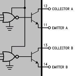
The 3524 datasheet shows that the PWM signal is generated by controlling the current flowing from pins 12 to 11
and from pins 13 to 14. In my design, pins 11 and 14 are connected to ground.
So, the PWM signal will ground pins 12 and 13. When these are grounded, current will flow through the MOSFET to the motor.
|
 |
|
The motor circuit uses a large electrolytic capacitor as a buffer. Diodes are used to help suppress any voltage spikes due to the inductive load of the motor. The final connection to the motor is the voltage reference that provides feedback to the 3524.
|
 |
Here is the complete schematic.
Here is a detailed photo.
click to enlarge/reduce
|


