| Disclaimer:The following are my notes. As I am learning electronics, I am making my notes available. I hope they will be of benefit. However, I do not guarantee the accuracy of my work. I recommend the reader exercise critical thinking.
|
PWM and MOSFET
Nov 14, 2008
For a while, I have been pondering
Switch Mode power supplies.
I recently made one with a 555 chip. I then did the same using the
Pulse Width Modulation (PWM)
feature of the
PIC18F4550 chip.
My source voltage was about 16 Volts. The PWM voltage was 5 Volts. I found that I could adjust the voltage
from about 10-16 volts, but I could not establish a voltage under approximately 10 volts. I broke out the oscilloscope
to see the pulses.
|
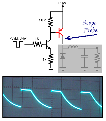
The pulses were discreet pulses from the PIC18F chip. The first transistor also exhibited nice, discreet pulses.
I used a PNP TIP42G for the power transistor.
On the oscilloscope, I saw my problem at this transistor.
The oscilloscope showed a solid, horizontal line representing the pulse. There is no clean cut-off after the
pulse. The voltage tapers off, and does not fall to zero before the next pulse.
|
|
I noticed that many power switching applications used
Power MOSFET transistors.
So, I decided to learn a little about them.
I learned that they switch much cleaner than the common
Bipolar Junction (BJT) Transistors.
My application would require a p-channel MOSFET.
However, RadioShack only carries the
n-channel IRF510.
I bought a couple of them because I heard they are very sensitive to static discharge.
|
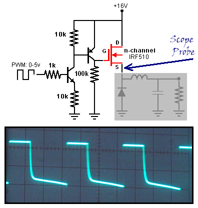
When the incoming pulse is at zero, I want there to be no power to the inductor. This required me to add an additional
transistor to invert the pulses. These two transistors are an NPN and a PNP BJT. They switch fast, but cannot carry
much current. The 10k and 100k resistors limit the current drain to about 700 micro Amps.
The IRF510 can switch fast and can handle about 4 Amps.
This pattern looks much better. You can see a sharper cut-off at the end of the pulse.
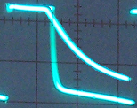
Here is a rough over-lay of the two signals. (Rough means I did this with cut-and-paste.)
|
|
|


