| Disclaimer:The following are my notes. As I am learning electronics, I am making my notes available. I hope they will be of benefit. However, I do not guarantee the accuracy of my work. I recommend the reader exercise critical thinking.
|
18F Setup
Microcontrollers: PIC18
The PIC18F4550 chip contains more features than the PIC16F including a module for USB communications.
There is some added complexity. The first issue to resolve is which chip to order.
The Microcontroller
The PICSTART Plus will program the 40 pin PIC18F4550-I/P chip.
The PIC18F4550 chip has some variants such as the PIC18LF4550-I/P and the PIC18F4550-I/ML.
I don't think these will work with the PICSTART Plus.
The PIC18F4550-I/P is available from www.newark.com
as part number 74K8623.
The Compiler and USB API
Unless you love assembly language, you will need to obtain a compiler. The company mikroElektronika sells compilers and hardware for PIC development.
The book Advanced PIC Microcontroller Projects in C includes a 2K limited version of the MikroC Compiler. I'm not sure what you can do with 2K on a PIC.
I have not tried this compiler yet.
There are open-source alternatives. I will spend more time on these later.
There is a project called, SDCC at SourceForge.
Here is a link to the article, Programming PICs in Linux using C with SDCC.
Microchip provides a student/demo version of the
MPLAB C Compiler for PIC18 MCUs.
After 60 days of install, some of optimizations and support for extended
instructions will be disabled.
This is the compiler I used to learn about these chips.
After installing the MPLAB C Compiler, there is some additional files you need to download from Microchip.
Microchip provides a USB Framework:
Microchip MCHPFSUSB v2.1 Installer.zip. This framework provides an API for USB communications.
The examples provided work with a demo boards.
For some reason, I like to do things the hard way. So, I had to build from their examples.
The installation of the Microchip MCHPFSUSB v2.1 framework will create many source directories. Two directories will be used later in this tutorial.
- \Microchip Solutions\Microchip
- \Microchip Solutions\USB Device - MCHPUSB - Generic Driver Demo\Generic Driver Demo - Firmware
The Hardware
The PIC18F4550 Datasheet gives a 430 page overview of the chip.
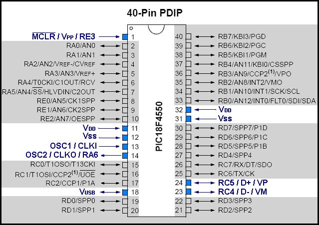
You will need to familiarize yourself with a few of the pins.
| Pin Name | Pin Number | Description |
| MCLR | 1 | Master Clear Reset |
| Vss | 12, 31 | Ground |
| Vdd | 11, 32 | Positive |
| Vusb | 18 | Output for internal
USB 3.3V regulator |
| OSC1 | 13 | Oscillator crystal input |
| OSC2 | 14 | Oscillator crystal output |
| D- | 24 | USB differential minus line |
| D+ | 25 | USB differential plus line |
|
|
 |
Oscillator Configurations
Section 2 of the data sheet details the oscillator configurations.
Where the PIC16F84A chip had four oscillator configurations,
the PIC18F4550 has 12 oscillator configurations.
You must put some thought into the configuration parameters if
you are planning to use the USB module.
I highly recommend reading sections 2.0 through 2.3 (a few times)
and study figure 2-1 from the data sheet.
Here is a helpful
list of pragma config statements
that I found on a
discussion thread.
Here is an example of the pragma entries that
define the oscillator configuration:
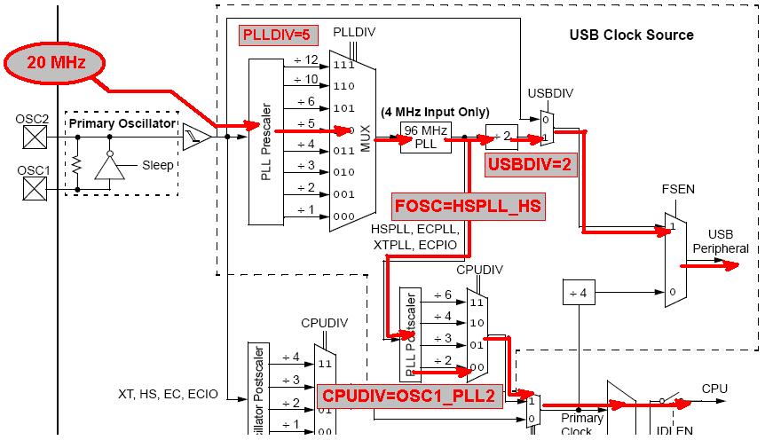
The first restriction to keep in mind is the 4 MHz input required for the
Phase Locked Loop (PLL) circuit.
The PLLDIV value gives you eight different ways to obtain 4 MHz. This is accomplished
by dividing the crystal frequency by the value specified in the PLLDIV pragma configuration.
You can bypass the PLL completely by choosing the oscillator frequency modes (FOSC)
of XT, HS, EC or ECIO. The HSPLL, XTPLL, ECPLL and ECPIO modes require the PLL circuit.
In my code, the statement #pragma config FOSC=HSPLL_HS
indicates the desire to enable the PLL circuit.
I used a 20 MHz crystal. In order to produce the the 4 MHz need for the PLL,
I selected PLLDIV=5. That is, 20/5=4 MHz.
|
              #pragma config FOSC=HSPLL_HS

              #pragma config PLLDIV=5

              #pragma config USBDIV=2

              #pragma config CPUDIV=OSC1_PLL2
|
|
|
The PLL circuit uses the 4 MHz input signal to generate a 96 MHz output signal.
This signal supplies two other circuits.
- The 96 MHz signal is divided by two to produce a 48 MHz signal.
The statement
#pragma config USBDIV=2 indicates
that the USB clock should use this 48 MHz signal.
- In HSPLL mode, the 96 MHz signal is also passed to a CPUDIV module that
can be configured to divide the signal by 2, 3, 4 or 6.
These correspond respectively to PLL2, PLL3, PLL4 and PLL6.
In HS mode (bypassing PLL), another CPUDIV module would receive input
from the crystal oscillator (OSC).
This CPUDIV module can divide the frequency by 1, 2, 3 or 4.
These correspond respectively to OSC1, OSC2, OSC3 and OSC4.
These parameters are combined together giving the four
combinations for the CPUDIV value: OSC1_PLL2, OSC2_PLL3, OSC3_PLL4 and OSC4_PLL6.
In the data sheet, figure 2-1 shows a logical diagram of the oscillator. Here is a "map"
showing my configuration using the diagram from figure 2-1:
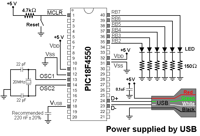
Schematic
Here is a schematic of my USB device. It is powered from the USB power supply.
When using power from the USB, you should keep usage under 100 mAmps.
UPDATE: I received a message from a friend in Australia who tried this example. He had
trouble getting it to work until he connected the USB case or shield wire to ground.
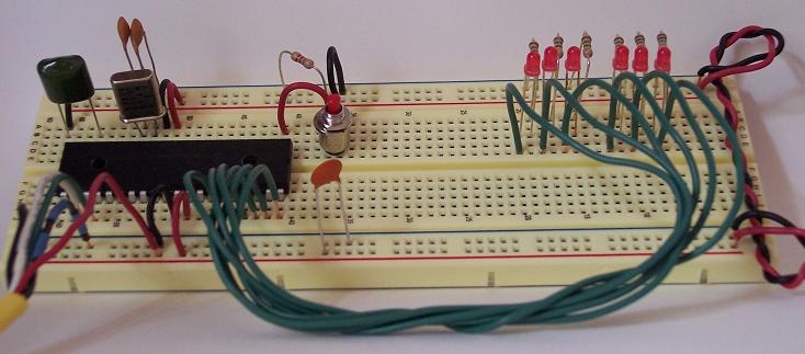
Here is a photo of the actual circuit. This image has balloon hot-spots.
|