| Disclaimer:The following are my notes. As I am learning electronics, I am making my notes available. I hope they will be of benefit. However, I do not guarantee the accuracy of my work. I recommend the reader exercise critical thinking.
|
Charger 14.4
March 15, 2010
My neighbor's drill charger stopped working. I found that the primary wires in the transformer were non-functional. This charger had a very simple design. It used a transformer, followed by a diode bridge and a larger resistor. The power supply indicated it delivered 17.4 volts DC @ 210 mAmps.
I was rather surprised to find such a simple charger for a Ni-Cd battery.
I understand that many methods for charging Ni-Cd batteries
attempt to detect the end-of-charge state.
One method is to observe the voltage rise during the charge cycle and then looking for a drop in voltage.
This drop in voltage indicates the end of the charge cycle.
A second method would be to measure the temperature of the battery.
NiCd batteries tend to generate heat at the end of the charge cycle.
In this application, I suspect the goal is to provide only a small amount of current toward the end of the charge cycle.
Since the original charger indicated it delivered 17.4 volts DC @ 210 mAmps, I decided I would try to replicate
these parameters.
A future project might be to control this circuit with a PIC Microcontroller.
This would include a method to control the current, observe the voltage, measure the temperature and track the time.
I began with a common Radio Shack 12-0-12 center tapped transformer.
When rectified to DC this produced
about 35 Volts.
I originally considered using an LM317 regulator to control the voltage and a resistor to control the current.
However, the heat dissipation would be significant. I would say about 4 Watts for a rough estimate.
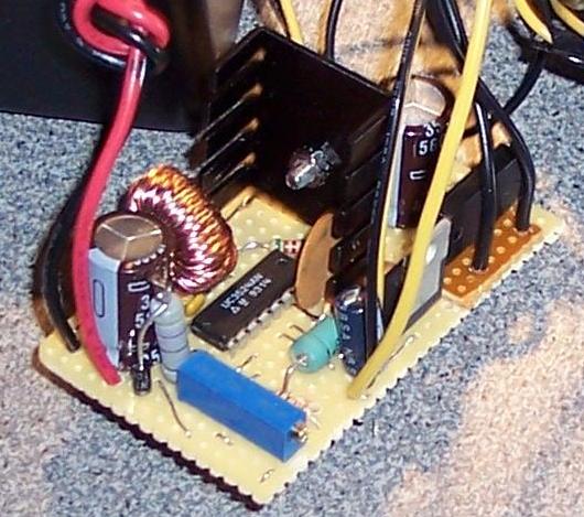
Instead, I made a pulse-width modulation circuit
in a buck configuration
using an LM3524 chip.
I used a potentiometer to select an
arbitrary voltage output.
I set this for an output of 17.4 Volts.
This configuration is more efficient than the LM317 regulator.
But, the power MOSFET generated a little heat, so I added a large heat sink to the MOSFET and a cooling fan for the unit. The Electronic Goldmine usually has a wide variety of fans at a good price.
All the fans I have operate from 12 volts. I connected the 35 volt source to the input of an LM7812 regulator.
I connected connected the ground to the center tap of the transformer.
I used the 12 volt regulated output to power a cooling fan.
|
click to enlarge/reduce
|
The LM3524 chip incorporates a simple current limiting feature.
Using pins 4 and 5, the chip measures the voltage drop across a small resistor placed in the path of the main power supply.
When the voltage drop across this resistor is greater than 200 mVolts, the chip reduces the pulse width.
When I tested a 1.8 Ohm resistor, I noticed that a short circuit generated about 200 mAmps.
I used two of these resistors in parallel to make a 0.9 Ohm current limiting resistor.
A short circuit results in about 500 mAmps.
When connected to a discharged battery, the current supply is around 200 mAmps. (To reduce the current, the user could clip out one of the two 1.8 Ohm resistors.)
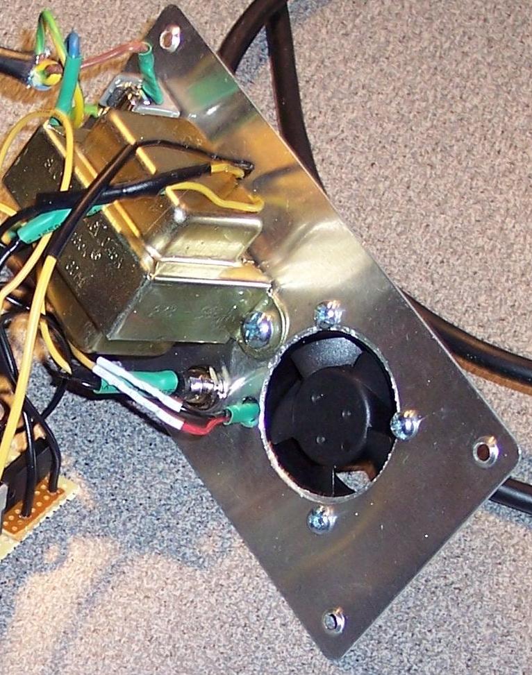
I packaged all this inside of a Radio Shack project enclosure.
I used a three wire computer power cable for power. The ground wire, a 1 Amp fuse, the fan and the transformer are bolted to the metal backplate.
I drilled a few holes in the plastic box for air flow across the MOSFET and added a few adhesive rubber feet. I also added a little LED as an "on" indicator.
|
click to enlarge/reduce
|
click to enlarge/reduce
|
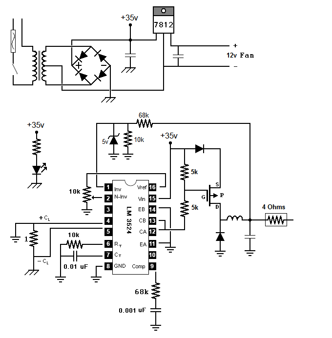
Here is the general schematic.
- The inductor for this project is an small hand-made toroidal inductor.
- I decided I did not need a large output capacitor.
- The two resistors at the base of P-MOSFET keeps the Vgs value within specifications for the IRF9530.
- The diode before the MOSFET prevents any battery current escaping back into the circuit when the unit is not powered.
This is not a perfect solution since a very small amount of current will be consumed by the resistors
that detect the voltage level.
- I added the 4 Ohm resistor to provide a little resistance to surge current and to allow the source voltage of 17.4 to be achievable. This resistor was cannibalized from a old computer power supply.
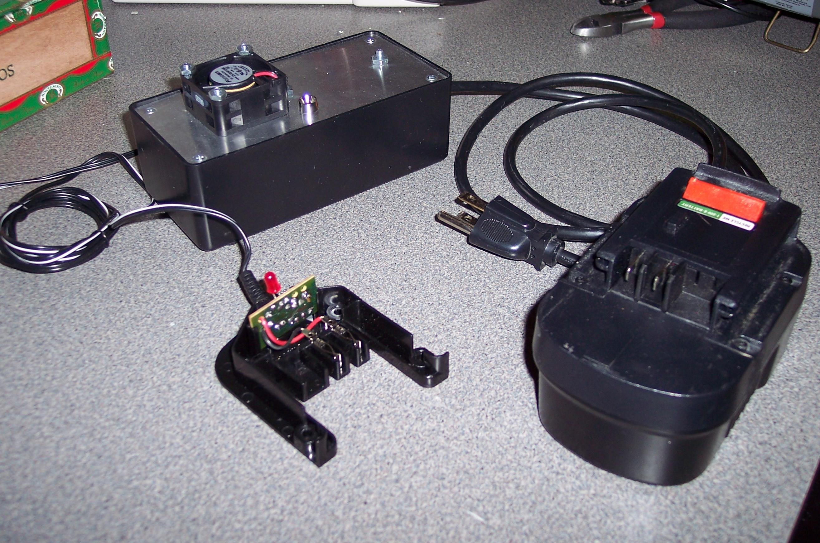
The original charger had a base unit that included the electronics and special connectors for the battery to snap into when charging. I reused this enclosure. I removed most of the components from the original circuit board and rewired it to work with the new charger. I also removed the old LED and added a new one with a 5k resistor.
I tested this with my 18 Volt drill battery and with the 14.4 Volt battery. It seems to gently charge the battery and not produce much heat.
|
Final
click to enlarge/reduce
|


