On/Off
April 25, 2010
On/Off
My electric truck requires a particular startup procedure. A small 12 Volt lawn mower battery powers the 12 Volt system
when the truck is turned off. When turned on, a DC-DC converter produces 14 Volts from the 144 Volt battery. This voltage
source feeds the 12 Volt system and helps charge the little 12 Volt battery. Next, the power controller turns on.
The controller activates the the final relay, and then it is ready to drive.
However, some problems can occur if the process is not followed.
I made a device to manage this startup process.
My first device used a voltage comparator
and many discrete components.
This was a fairly complex setup, and it worked for a while.
Last week, the device malfunctioned.
I studied the device and found a race condition.
I'm surprised this had not surfaced earlier.
Last year, I designed a second version shortly after I finished the first one.
This second design used a Microcontroller.
I tried to integrate too many sensors and I/O ports. I even made a Linux USB driver for the device.
But, this was a little too complex so I scrapped the idea.
I needed to get something done quickly so I could get the truck back on the road.
So, I revisited the microcontroller idea and developed a simpler design.
The new design uses a PIC18F4550 Microcontroller.
I am amazed at the reduced complexity of the circuitry compared with first design in which the logic
was controlled by discrete components. Although, the microcontroller design does require firmware development.
But, I enjoy programming too.
I needed to quickly develop and deploy this device, so I retained many of the concepts of the original device.
I plan to make another device this summer that may significantly modify everything.
Here is the basic layout of the high current, high voltage system of my truck:
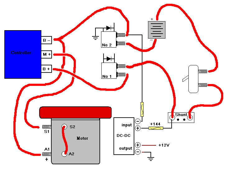
The Order
Here are some rules that I need to follow: I should provide the +144 Volts to the controller before sending it +12 Volts. In each case, the ground must be connected first.
When the controller is happy, it will then activate a contactor (relay).
I also use a DC-DC converter. I should make sure that it is stabilized before attempting to turn the controller on.
Furthermore, I should disable all 12 Volt systems when powering-up the controller.
There are some additional rules, but I will integrate those specifications later.
So here is the basic order:
- Turn Key On - The Unswitched 12V system is now connected to the Switched 12V system.
- Activate Contactor Number 2 (NO2C)
- Turn on DC-DC converter
- Press Start Button
- Disconnect Unswitched 12V system
- Send +144V to controller
- Send +12V to controller
- Wait for controller to activate contactor (NO1C)
- Engage the Switched 12V system.
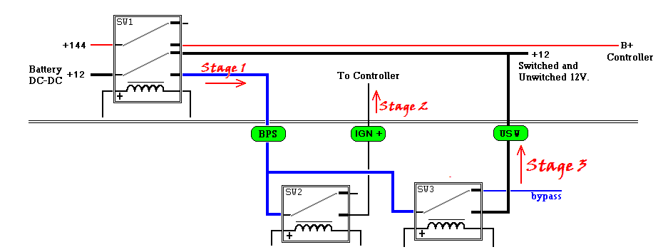
I decided to model my first design around three stages.
When the key is turned, +12V is sent to the switched 12V system.
In stage 1, the +12V supply is disconnected from everything.
In stage 2, the +12V supply is sent to the controller only.
Stage 3 returns power to the 12 volt system.
Three relays control these stages. I retained this model for my new design.
I don't know whether I will use these relays in the future.
|
Relays
Stage 1: SW1 is a double pole, double through (DPDT) relay.
When SW1 engages, +144 Volts is sent to the B+ input of the controller,
and +12V is removed from all 12 volt systems.
Stage 2: After a short delay (to ensure the DC-DC converter is happy),
relay SW2 engages to send the +12 Volts to the controller.
Stage 3: The controller signals when ready to operate.
On this signal, SW3 switches power back to the +12 Volt system. (Before SW3 engages,
12 Volts can be drawn from the first pole of the relay. I call this "Bypass" source.)
|
click to enlarge/reduce
More than anything else, this project showed me the difference between the analog and digital solutions.
My first design implemented the logic using discrete components. With the microcontroller, I only need to
make a driver for the relay and connect the driver to the microcontroller.
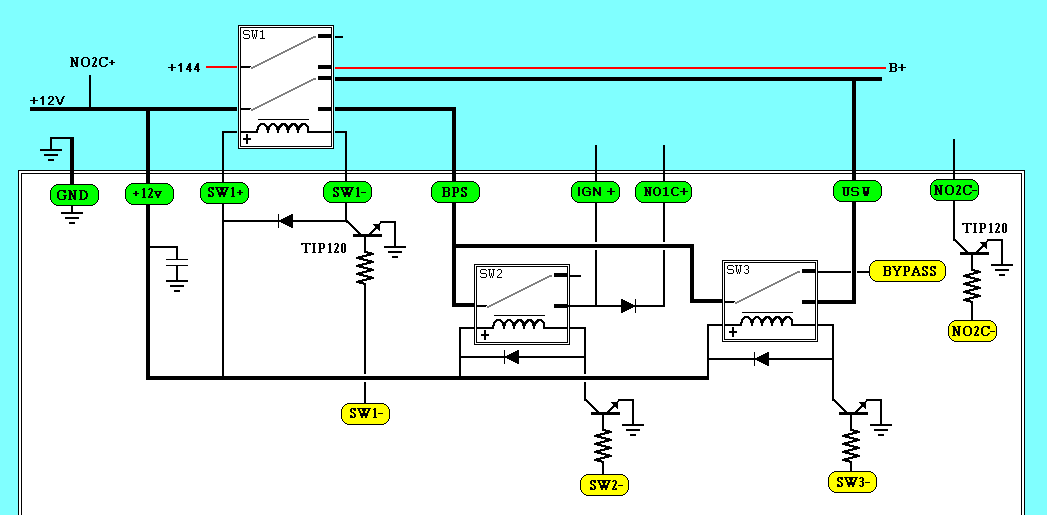
The next figure shows the drivers for the relays.
The yellow SW1-, SW2-, SW3- and NO2C- indicate a connection to "digital output" pins on the microcontroller.
The green tags represents external connections.
This figure also shows what components will be contained in the box enclosure.
The light blue indicates the outside of the box, the white is the inside of the box.
I will probably move the one outside relay to the inside in a future design.
|
External Connections
| GND | Frame ground for the 12 volt system. |
| +12V | Unswitched +12 (always on) |
| SW1+ | Positive connection for the switch SW1 |
| SW1- | Negative connection for the switch SW1 |
| BPS | 12 Volt Bypass Circuit |
| IGN+ | 12 Volt supply for the IGN port of the controller |
| NO1C+ | 12 Volt for the Number 1 Contactor |
| USW | When in Bypass mode, the output will provide
power to the unswitched 12 volt system. |
| NO2C- | Ground for the Number 2 Contactor |
|
click to enlarge/reduce
|
click to enlarge/reduce
|
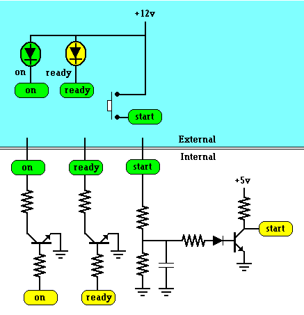
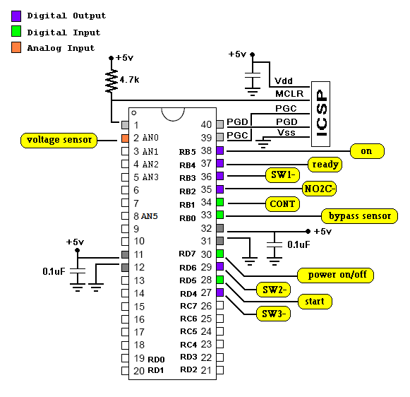
I incorporated a couple of LEDs on the dash board to indicate "ready" and "on". I also have a start button.
The yellow tags indicate connections to the microcontroller.
The two LED drivers are connected to "digital output" microcontroller pins.
The start is connected to a "digital input" pin.
|
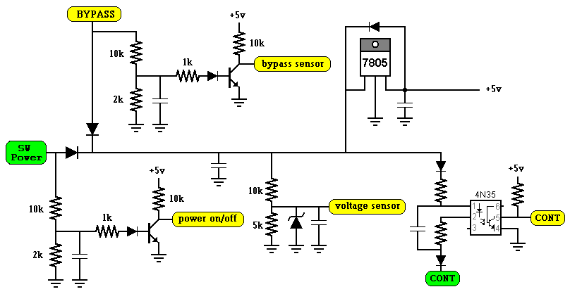
When the key is turned on, power enters the circuit through the input labeled "SW Power".
A circuit monitors this input and generates a digital signal for the microcontroller to indicate whether the key is on or off.
A similar circuit monitors the bypass mode supply.
Two diodes merge these supplies to form the main power supply.
Another circuit monitors this supply using an analog scale.
The microcontroller reads this value with an analog to digital converter.
The LM7805 provides a regulated 5 volt supply for the microcontroller.
The capacitors allow the microcontroller to operate a few seconds after the main 12 volt power is turned off.
This facilitates a predictable shutdown process.
When the power controller is ready to operate, it will ground the green external connection labeled CONT.
I use an optocoupler and a few diodes to ensure that no voltage spikes or noise enters the 5 volt system.
The yellow CONT is a digital input to the microcontroller
NOTE: I changed to 2k resistors to 5k resistors. This allows it to operate at lower voltages.
|
The final component in this design is the microcontroller.
The PIC18F chips can operate using an internal 8MHz clock.
This eliminates the need for an external oscillator.
I recently purchased a PIC Kit 3.
I no longer have to remove the PIC chip to update the firmware.
I added an Ethernet cable with an RJ11 connector to my setup so
I can update the firmware using the In Circuit Serial Programmer (ICSP).
Here is a copy of the firmware C code.
The code is fairly simple ... The Microcontroller is probably really bored.
In the near future, I hope to add an input to monitor whether the 144 Volt system is engaged, and
I hope to add a input to determine if the charger is active.
I may revisit the idea of the USB connection.
And, I will make a real printed circuit board.
|
|
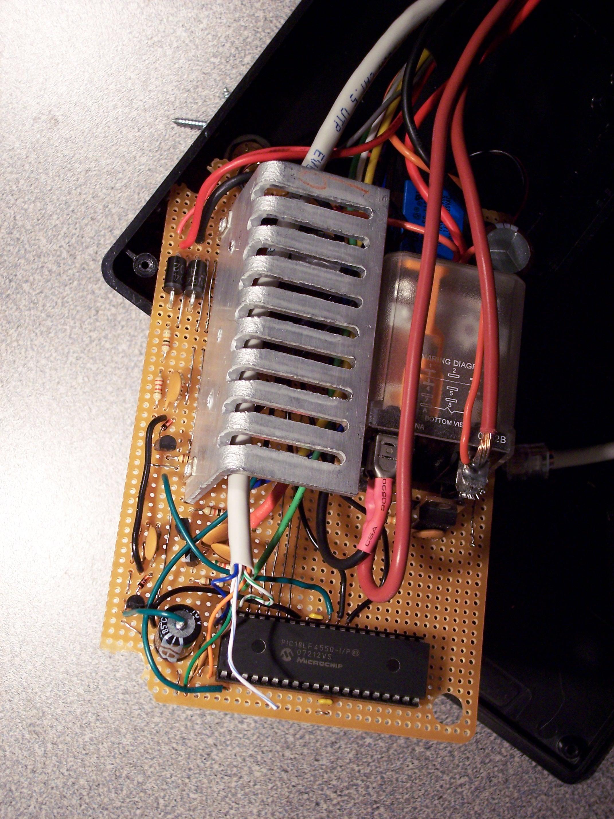
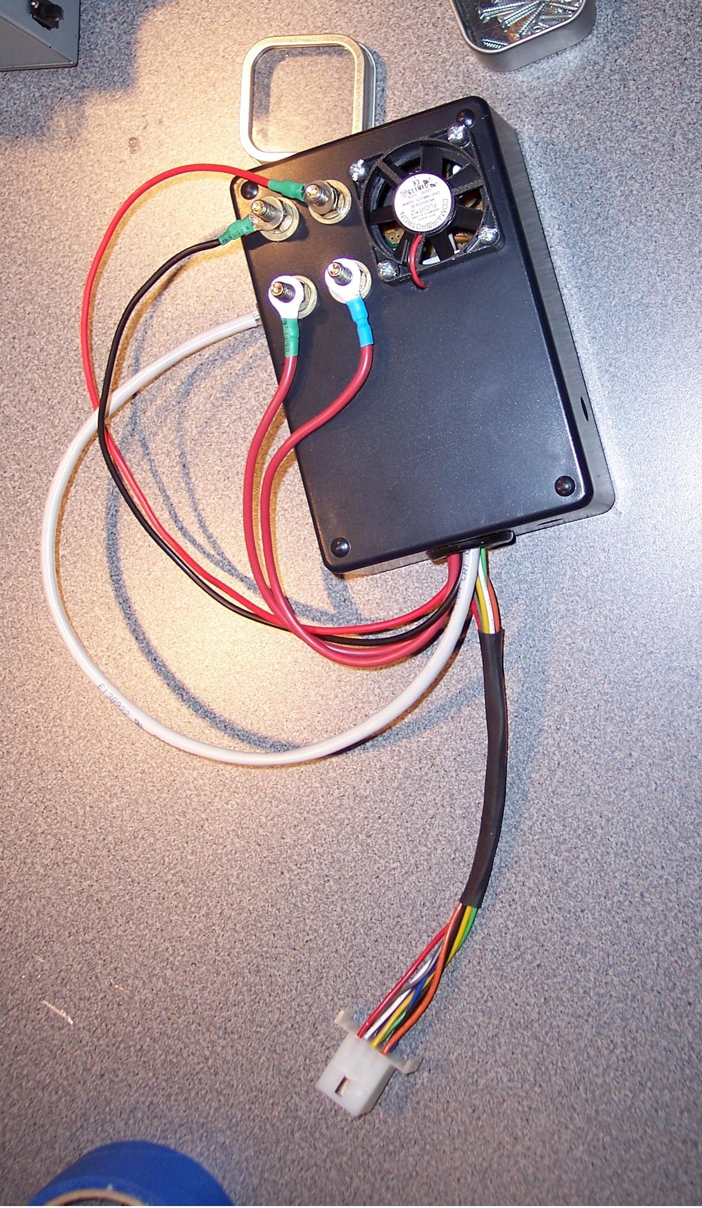
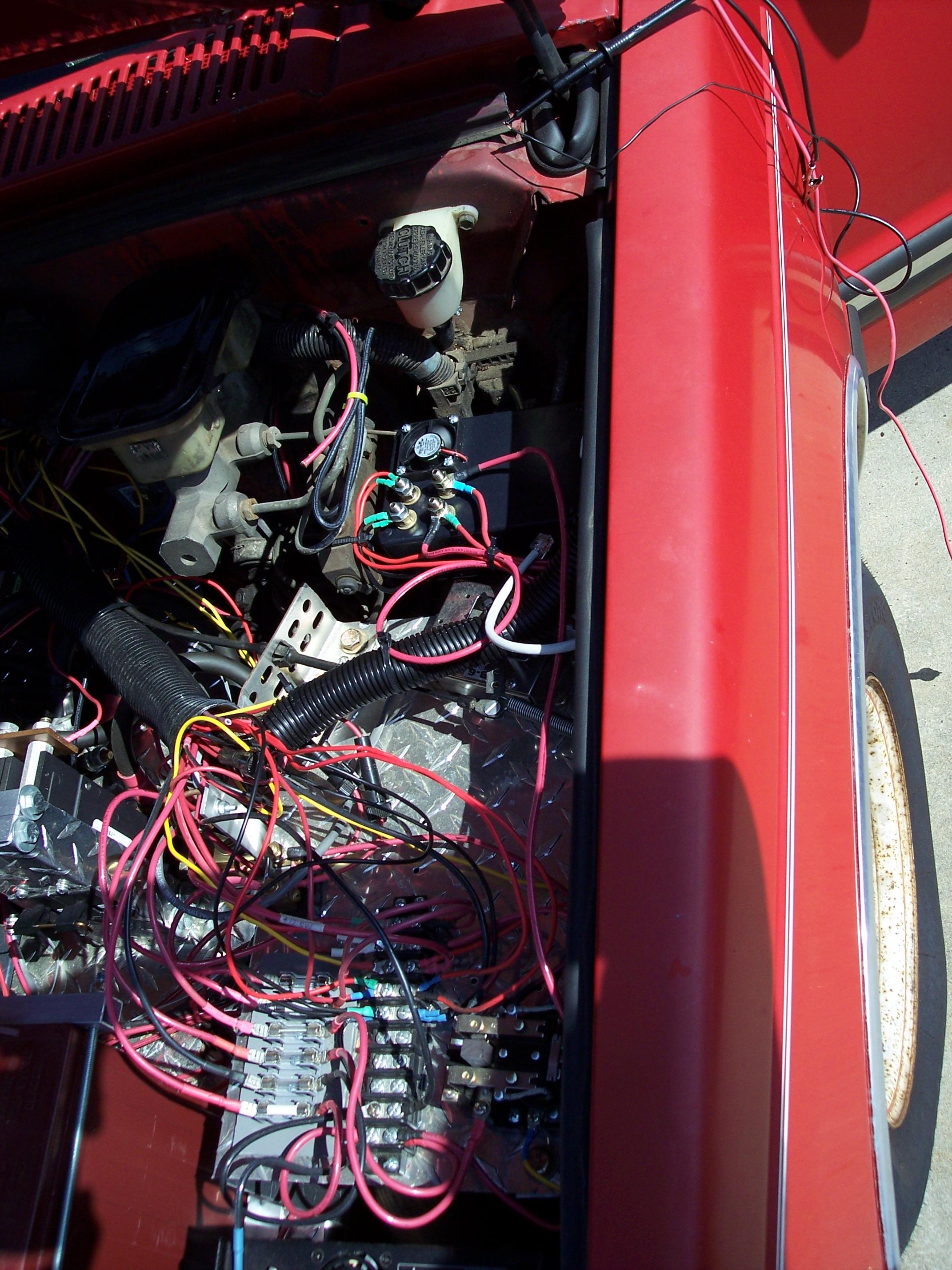
Here are a few photos of the finished product:
click to enlarge/reduce
|
click to enlarge/reduce
|
click to enlarge/reduce
|
|


