|
|
| Disclaimer:The following are my notes. As I am learning electronics, I am making my notes available. I hope they will be of benefit. However, I do not guarantee the accuracy of my work. I recommend the reader exercise critical thinking.
|
Input Trigger
Power Switch
The 7805 and 7812 regulators require the source voltage to be
at least two volts over the regulated value. I wanted to add
a circuit to send voltage to the regulator only when the source
is over 7 volts.
|
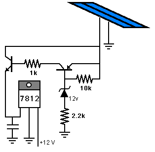
I went through many iterations of ideas. I considered using a
Zener diode. This image shows one idea I had seen on the web.
I wanted a sharp turn on and a sharp turn off. This one did
not provide firm switching.
Click here for simulation.
|
 |
I considered using a voltage comparator. But, I only had quad comparator
chips, and I felt this was over-kill.
I considered using the same quad comparator and power the comparator
from the source voltage instead of the regulated voltage. But, I
did not like the comparator having a continuously variable power source.
I considered using an op-amp. Then I learned they often need fine
tuning. I explored many other ideas and finally settled on one.
I settled on a transistor Schmitt Trigger. I use a Schmitt Trigger with
the comparator to determine the on/off values for the charging system.
This new trigger is made of discrete transistors instead of a comparator.
The advantage of using a Schmitt Trigger is that the on/off switching
is very firm.
|
Here are some helpful references for Schmitt Triggers:
My application uses a 5 Volt Zener diode to set the source voltage
for the trigger.
Very little current is used, so the Zener should be sufficient.
The varying input to the trigger is dependent on the voltage
from the solar panel.
This voltage is scaled down using a voltage divider of resistors.
The trigger's output is either 5 volts or something very small (< 1 volt).
|
 |
The output from the Schmitt Trigger will determine whether power should be
sent to the regulator. It took a few transistors to make this happen.
The first transistor operates within the 5 Volts regulated by the Zener.
This transistor must not interfere with the Schmitt Trigger. The second
transistor operates relative to the source voltage from the solar panel.
The third transistor inverts the signal. The fourth transistor is the power
transistor that feeds the regulator.

Click here for simulation.
The simulation has two 100 nF capacitors. These are not necessary but are added to assist the convergence of the simulation.
|
|


