| Disclaimer:The following are my notes. As I am learning electronics, I am making my notes available. I hope they will be of benefit. However, I do not guarantee the accuracy of my work. I recommend the reader exercise critical thinking.
|
Truck
May 13, 2008
Disclaimer: This is my experiment.
Warning: Improper charging techniques can cause a battery to explode.
|
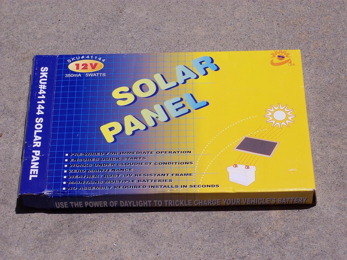
This weekend, I bought a solar panel at a hardware store for about $40. I wanted to experiment with
solar panels, so I figured I would give it a try. I did not know what I would do with it, but I
thought it would be a fun toy.
The box indicated it was capable of charging a car battery. It produces 12 volts and 350 mAmps.
But, I generally don't believe boxes.
|
|
|
I don't drive my truck as much as necessary to keep the battery charged. Many times, I've had to
pull the battery out to charge it. It takes a while to remove and install the battery.
I gouge up the clamps. The charging takes all day. This is a major inconvenience.
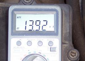
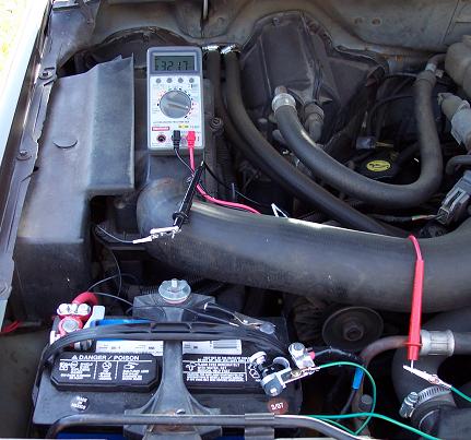
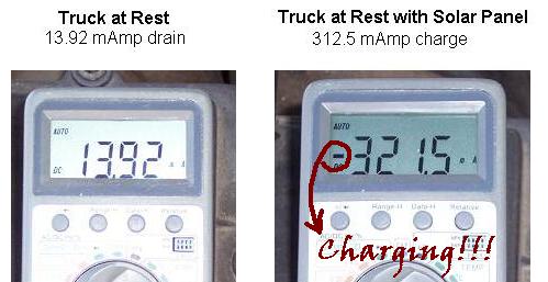
I put my multi-meter in-line with the negative battery terminal and cable. With nothing on, the
truck was using 13.92 mAmps. Not sure what the truck is doing, but it is consuming energy.
The box indicates the panel can produce up to 350 mAmps. I figured
the current from the panel should at least offset this energy drain.
Value at Rest
|
|
|
|
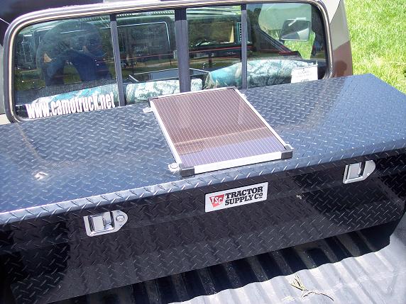
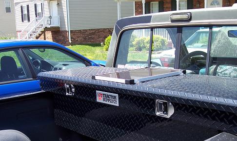
I decided to mount the panel to the top of the tool box. I used a weather strip and a rubber washer
to hopefully
prevent water leaking into the tool box. I added a connector and ran some wires under the truck
to the engine compartment.
I connect the positive wire to a hot line I ran for another project. I connected the negative
line to ground. The box indicates the panel has a built-in diode so it should not reverse and take
power from the battery at night. I added a 1 Amp fuse just in case a short occurs.
|
|
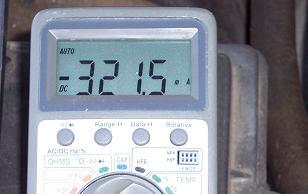
The final test indicates -321.50 mAmps. Notice the minus (-) sign. This means the current is in the
reverse direction from the previous reading. So, 321.50 mAmps is being sent to the battery. Not only
is the solar panel meeting the 13.92 mAmps drain at rest, but it is providing
321.50 mAmps to charge the battery. The total current produced by the panel is 321.50 + 13.92 = 335.42 mAmps.
This is a just a little less than the 350 mAmps on the box.
I finished the install late in the evening. Even without direct sun, it still produced enough current to cover
the continuous 13.92 mAmp current drain.
I guess time will tell whether this actually works.
|
|
Is this safe?
Now, the big question is, will this rate of charge over-charge the battery?
I had a friend warn me of the potential for hydrogen explosion.
So, I am now learning about charge rates and how to limit over-charging.
|
|
Update
|
I still don't know whether this one panel would cause the battery to explode.
I searched some web sites to see what I could learn about charge rates for
car batteries. To the right are some of the web sites I found about battery charging.
My battery is an Autocraft Silver battery with a Reserve Capacity (RC) rating of 86.
This means it could operate a 25 Amp device for 86 minutes before dropping to 10.5 Volts.
One of the above web sites indicates that the Amp-Hour rating can be estimated by
Amp-Hour = RC/2 +16.
This means my battery is about 60 Amp Hours. Another site indicates that you can safely
charge a rechargeable battery at 10% the Amp-Hour rate. So, the 60 Amp Hour battery
can safely charge at 6 Amps.
|
|
|
The solar panel provides about 335 mAmps when in bright sun.
At this rate, it would take about 18 of them to produce 6 Amps.
This makes me feel safer about the setup.
However, over-charging a battery will reduce the life of the battery.
For example, Hydrogen is produced when a battery is over-charged.
Concentrated Hydrogen will explode like the Hindenburg.
This is probably one of the more dramatic ways that over-charging a battery can reduce its lifespan.
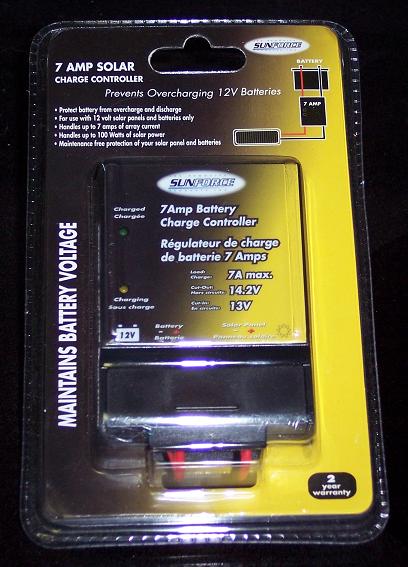
SunForce makes a 7 Amp Solar Charge Controller used
to protect batteries when charging with solar power. The solar panels feed into this device, and
the device feeds the battery. Over-charging is prevented by automatically disconnecting the circuit when
the battery reaches 14.2 Volts.
I added the 7 Amp charge controller to the system today. The chance of the battery exploding is greatly
reduced by using this charge controller and by keeping the charge rate under 6 Amps.
The logical conclusion is that I should add about 15 more panels!
|
|
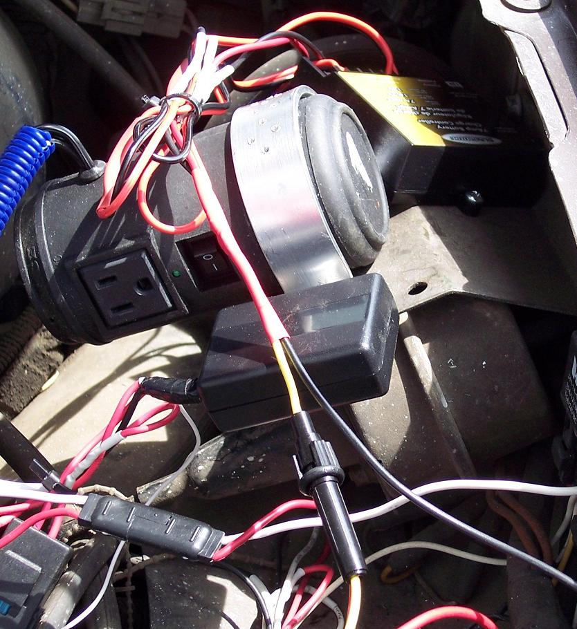
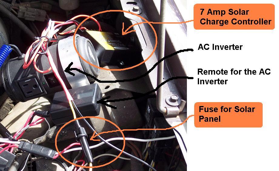
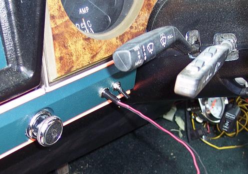
It is getting a little crowded under the hood. Here is a photo of the wiring for this project.
You can also see the components of my remote-controlled AC inverter. I added this a couple of
years ago so I could add some Christmas lights to my truck.
Update 2
|
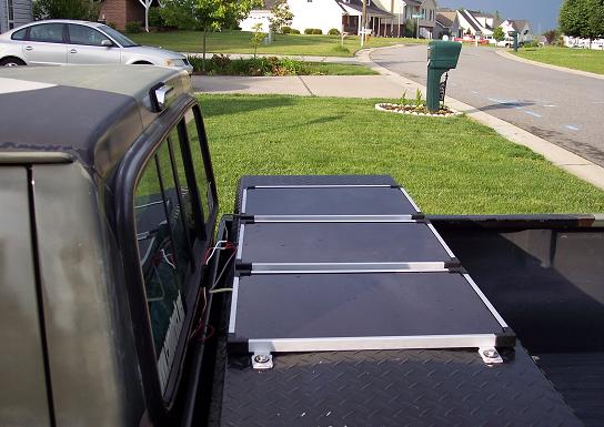
With the charge controller protecting the battery from over-charging, I decided to buy two more panels.
I cut two aluminum straps to mount the three panels and bolted the unit to the tool box.
The three panels are wired in parallel: Same voltage, more Amps.
|
|
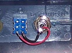
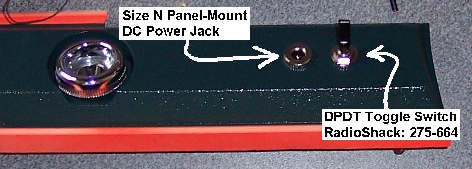
I wanted the ability to turn the charging system off. I also thought it would be neat to
use the solar power for other purposes. I bought a double-pole double-through (DPDT) center off
toggle switch from RadioShack. The positive and negative feeds from the Solar panels connect to the center of this switch. In the center position, the switch disconnects both the positive and negative feeds from the panels. In the lower position, both feeds are sent to the charge controller. I mounted a DC Power Jack (Size N) beside the switch. When the toggle switch is in the up position, the positive and negative
from the panels activate the DC Power Jack.
|
|
|
Now I have a solar DC power source:
A good 8 to 19 volts of unpredictable current!
Not sure what I will do with it, but it should provide much amusement.
|
Update 3
|
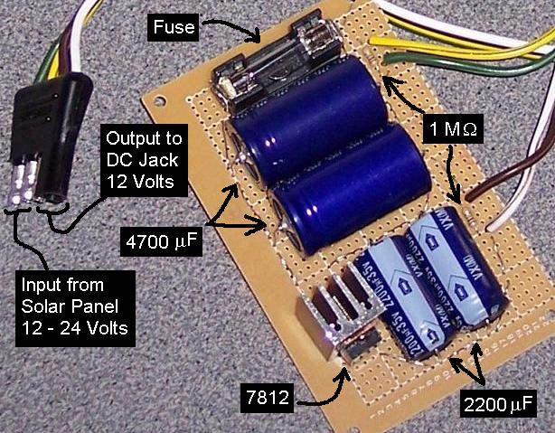
I built a circuit to condition and regulate the power for the DC jack. I bought two
4700 uF capacitors, two 2200 uF capacitors and a 7812 regulator. The output from the
DPDT switch feeds this circuit. A fuse is built into the circuit. Hopefully, the
capacitors will maintain some charge when clouds pass over the panels.
The 7812 regulator maintains a consistent 12 Volts. The two 1 Mega Ohm resistors
will slowly drain the large capacitors when the load is removed and the switch is
off.
The DC Power Jack now provides fairly stable power.
|
|
Here is a schematic close to my current configuration.
|
|
Here is a photo of the power conditioning circuit.
|
Update 4
November 14, 2008
It has been many months since I put the solar battery charger on my truck. Recently, I've had a few
weeks where I was not able to drive the truck.
However, when I went to crank it after setting for two weeks... it fired right up! Awesome!
So, I say this project was a success.
|