Tracker 1
Nov 21, 2009
I setup an experiment last year to observe the charging of a battery from a solar panel. I setup
a device to measure the light intensity, the voltage of the battery and a few other parameters.
The data was logged and then graphed. I had quite a few bugs in the system, but the one thing
that was evident is that direct sunlight makes a huge difference.
Many sites on the Internet that indicate a solar tracking system increases performance by 40%.
I found quite a few schematics for solar trackers on the Internet.
The basic tracking system attempts to maintain a balance between two light sensitive resistors.
Some of the designs I found are quite powerful. Here is
an example of a solar tracker
using a Arduino. The Arduino is a prototyping platform based
on an Atmel Microcontroller.
The BEAM project describes a simple design
called a BEAM Head. This design is
a combination of science and art. I will definitely explore this idea later on.
I also found many examples using OP Amps. I had never used OP Amps, so I thought this would be a good
time to get acquainted with them.
The basic idea is to keep the voltage drop the same across the photoresistors. However, it is easy to
get into a cycle where the system repeatedly over compensates. I found this jittering
jittering system on youtube.
To prevent this jitter, I decided to implement a type of hysteresis to produce a buffer region where
the motor would be off. The design given here includes this feature.
click to enlarge/reduce
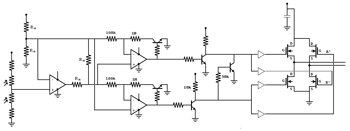 I found it difficult to attain an accurate tracker that was free of jitter. In low light conditions, I can
use a 1M Ohm resistor to attain a fairly good system. When I take the system outside, I found I needed a
10M Ohm resistor to attain an accurate system. At this point, I wonder if the hysteresis is providing any
effect at all. Here is a link to a rough
simulation of this circuit.
The sliders on the right ("Top" and "Bottom") simulate the two photo resistors.
My next plan will be the BEAM design or a microcontroller based system.
I found it difficult to attain an accurate tracker that was free of jitter. In low light conditions, I can
use a 1M Ohm resistor to attain a fairly good system. When I take the system outside, I found I needed a
10M Ohm resistor to attain an accurate system. At this point, I wonder if the hysteresis is providing any
effect at all. Here is a link to a rough
simulation of this circuit.
The sliders on the right ("Top" and "Bottom") simulate the two photo resistors.
My next plan will be the BEAM design or a microcontroller based system.
|
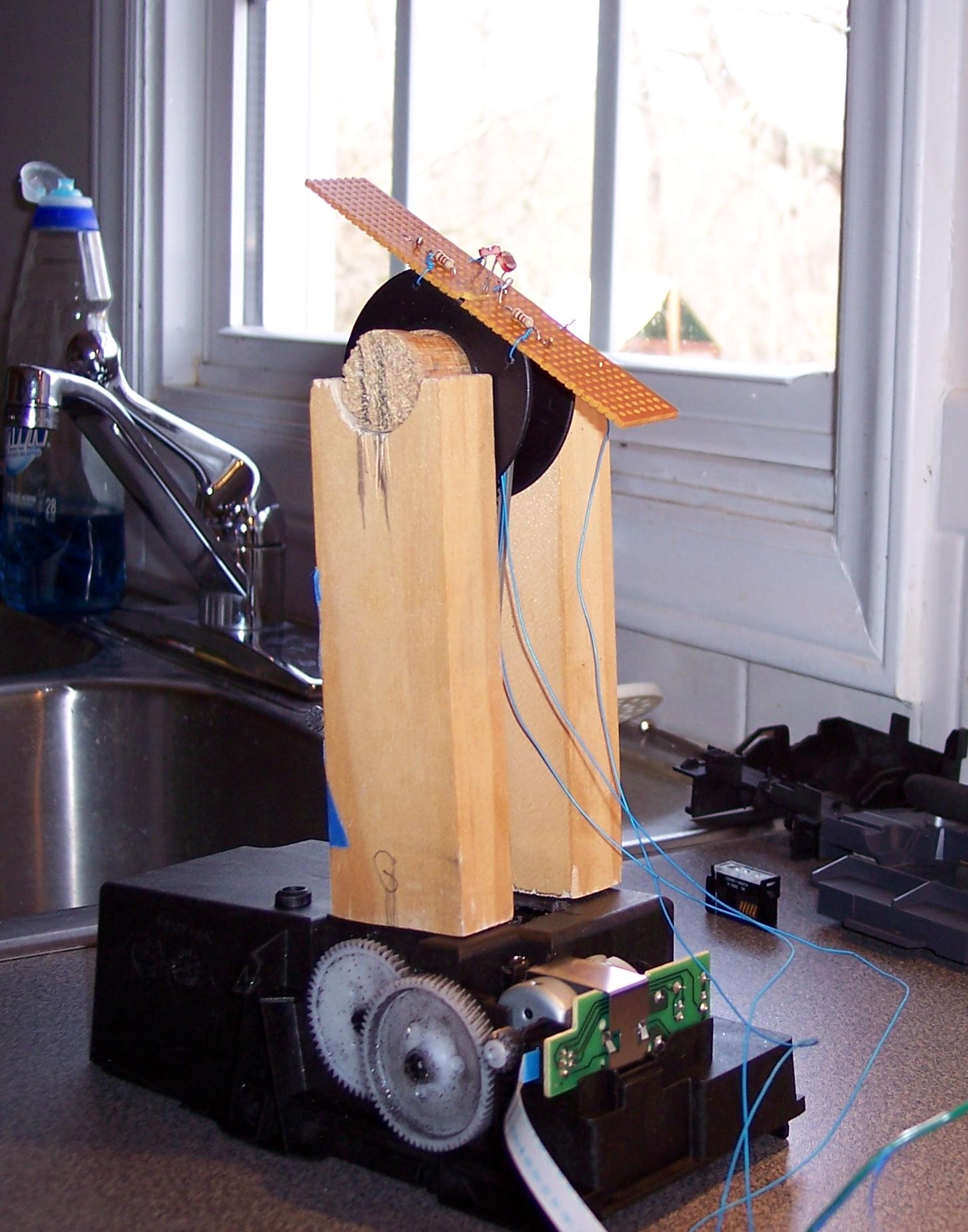
Here are the moving parts. The motor and gear assembly come from an broken printer that someone
gave me. I like old printers. I found that they contain a good collection motors and gears. The
head is made from part of an old flag pole, scrap generic circuit boards and a wire spool.
Two photoresistors mounted to the circuit board measure the light levels.
The band connecting the spool to the gears is also from the printer. I cut it to length and sewed it together.
On the back of the motor is an interrupt sensor that can be used to determine the number
of "step" the motor turns. I have ideas about possibly using this with a Microcontroller.
click to enlarge/reduce
|
click to enlarge/reduce
|
Here is a video of the system. In this video, I turn on and off a light on the cabinet.
|


