|
|
Tracker 3
Dec 17, 2009
|
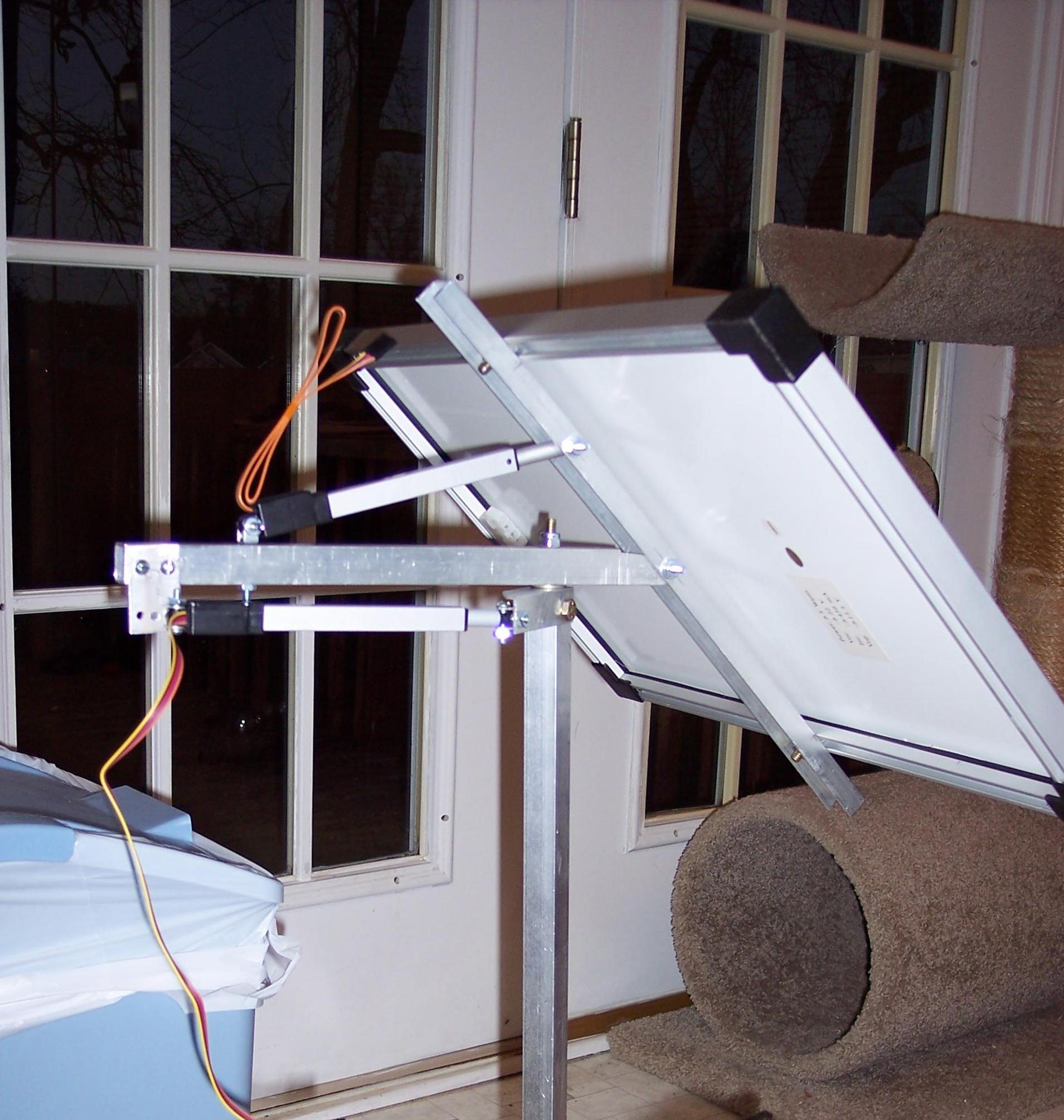
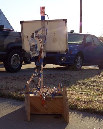
I continued the solar tracking system development into a two-axis version. I figured it was time
to see if the tracker could be powered from the actual solar panel. So, the tracker is much bigger
than in my previous experiments.
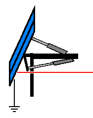
I began by making the two-axis mechanical system. I used square tube aluminum and some bolts.
Nothing fancy here.
|
|
click to enlarge/reduce
|
I attached the linear actuators as I built the mechanical setup. I had to take some time to do the
math to figure out how to place the actuators to get a good range of motion. I planned for close
to 180 degrees horizontal and close to 90 degrees vertical.
|
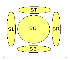
I complimented the sensor with two additional sensors. I call them Sensor Right, Left, Top, Bottom and Center.
The algorithm attempts to keep the voltage of the L/R and T/B equal, and keep the Center greater than all the other sensors. As the system narrows in on the direction, Pulse Width Modulation prevent overshooting the position.
The linear actuators contain built-in potentiometers that indicates the
position of the linear actuator. This feedback to the microcontroller
prevents the linear actuator from over-extending. I also use this to adjust
the panel in a neutral position when the light levels are too low.
Since I have two linear actuators, I now how two position sensors: Sensor Position 1 and Sensor Position 2.
Throughout this project, my biggest challenge was keeping the naming consistent and intuitive.
|
|
|
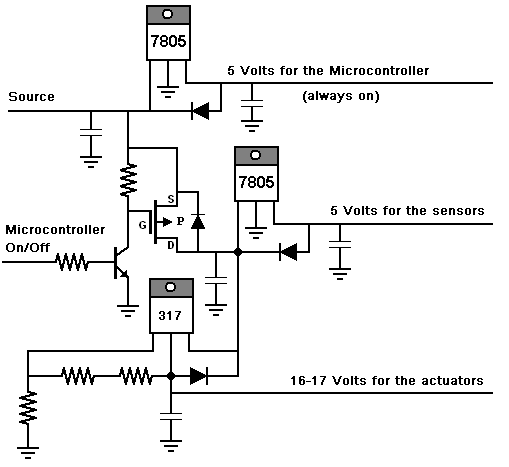
I added a sleep/wake cycle to conserve power. The system will sleep for a few seconds
then wake for a few seconds. During the sleep mode, the power is off to the sensors.
The microcontroller turns this external power system on and off. This power system
contains a 5 volt source for the sensors and a 17 volt source for the actuators.
The H-Bridge is setup should reduce this 17 volts to about 12 volts.
It currently has an occasional Myoclonus jerk when it
wakes up.
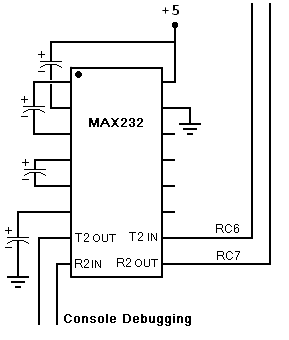
During the testing, I really needed to know more debugging information than what a couple of LEDs
could indicate. So, I investigated the UART feature of the PIC18F chip. I had ordered some MAX232
chips about a year ago. I finally got a chance to use them. This addition was fairly simple.
So, the device now has a serial debugging port for an old-fashion serial terminal.
|
|
Place the mouse over the image to view a time-laps photo.
It may take it a second or two to start.
The Pepsi bottle is a counter-weight. When it is balanced, it is easier to turn.
|
|


