| Disclaimer:The following are my notes. As I am learning electronics, I am making my notes available. I hope they will be of benefit. However, I do not guarantee the accuracy of my work. I recommend the reader exercise critical thinking.
|
Power
My thermostat circuit is fairly basic. When the temperature passes a threshold,
a relay will close providing power to the fans.
I had a periodic problem with relay chatter. When the fan kicked-in, the relay
would click a few times before stabilizing. I spent many hours trying to
figure out the cause.
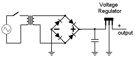
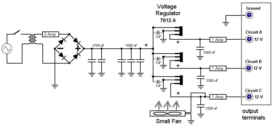
My power supply consisted of a 120 volt to 12.6 volt AC transformer,
followed by a rectifier, followed by capacitors and a voltage regulator.
In an attempt to explain the relay chatter, I considered the voltage ripple
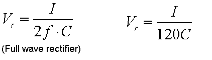
as a cause. I found an equation for voltage ripple. With a full wave bridge rectifier operating
on a 60 Hz source, the equation is equation becomes current/(2 * 60 * capacitance).
My initial design included a single capacitor of 470 uF.
A single fan pulls about 200 mAmp. This means the
voltage ripple would be about (0.2 Amp)/(120*470 uF) = 3.55 volts.
This could cause all kinds of problems with my 12 volt circuit.
I needed to account for the the significant impact of voltage ripple when powering
all the fans pulling 2 to 3 Amps.
The transformer is a 120 volt AC to 12.6 volt AC transformer. When I measured the output,
it actually read 14.0 volts AC on my digital meter. Next, I pass this through a fuse and
then to a full wave bridge rectifier.
When building the system, I tested the output of the rectifier with a 220 uF, 30v
capacitor and no load on the system. I found the DC voltage to be 17 volts!
This puzzled me -- I forgot about the Root Mean Square voltage rating system for
AC voltage. For example, a 120 volt outlet has an average, or Root Mean Squared,
voltage of 120 volts. The peaks of the AC oscillations are actually
about 120 * 1.414 volts, about 170 volts.
Let's assume we have 12.6 RMS voltage from the transformer. If I calculate the
peak voltage, 12.6*1.414, I get about 17.8. Factor in a diode drop
or two for the bridge and I come close to the value I measured at the capacitor.
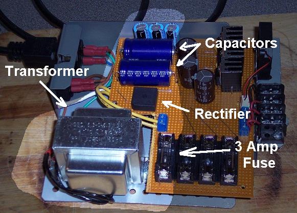
I decided to use two 4700 uF and three 1000 uF capacitors for a total of 12400 uF!
The voltage ripple for 3 Amps is now estimated at (3.0 Amp)/(120*12400 uF) = 2.0 volts.
I measured 17.3 volts DC at the capacitors. A ripple of 2.0 volts could bring my voltage down to 15.3.
The 12 volt regulator requires at least 14 volts input. I hope this problem is solved.
|
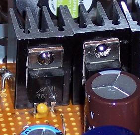
I found some datasheets for the 7812 voltage regulator.
The sheet from Motorola
recommends an input bypass capacitor under certain conditions (page 14). Just in case,
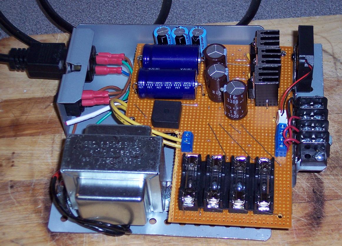
I used a 1.0 uF tantalum capacitor beside each voltage regulator. This is the little yellow thing
at the base of the voltage regulator.
The three voltage regulators for three separate circuits. An additional 3300 uF capacitor follows each regulator. I recently learned the value of fuses, so each circuit contains a one Amp fuse between the capacitor and the output terminal.
|
 |
|


