| Disclaimer:The following are my notes. As I am learning electronics, I am making my notes available. I hope they will be of benefit. However, I do not guarantee the accuracy of my work. I recommend the reader exercise critical thinking.
|
Thermostat
UPDATE: Aug 16, 2010: After a couple of years working with electronics, I see quite a few things I would change. I should revisit this project, but I will leave this page on the web for reference.
April, 2008
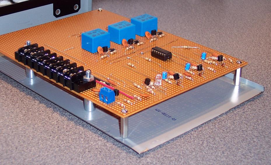
This is the thermostat circuit I built to activate the cooling fans for the entertainment I built.
This design is inspired by
this web page.
Here is a mouse-overable-balloon image.
|
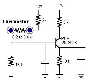
Thermistor Amplifier
The original design for the thermistor amplifier system used
a common-emitter amplifier
circuit with an NPN transistor.
I obtained about 2 volts when the thermistor registered about 3k and about 10 volts when the
thermistor registered 100 Ohms.
As I assembled a test circuit, I realized I needed the high voltage when the resistance was low.
I redesigned the circuit to use a PNP transistor.
Here is a simulation
of this design.
The voltage output ranges from 3 to 9 Volts, and the
current through the thermistor is less than 1 mAmp.
|
|
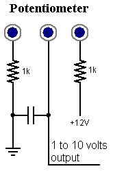
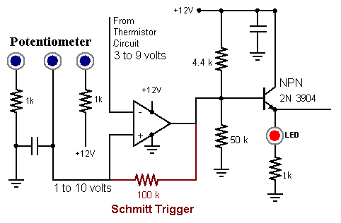
Potentiometer and Voltage Comparator
|
A 10 kOhm potentiometer is connected to ground with a 1k resistor and connected to +12 with a
1k resistor. This produces a reference voltage that ranges from 1 to 10 volts. This will serve
as the temperature adjustment.
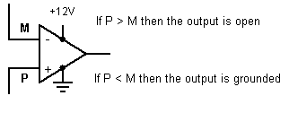
A voltage comparator will compare the output voltage from the thermistor circuit with
the voltage set by the potentiometer.
A voltage comparator has two inputs, one labeled plus (+) and the other labeled minus (-).
The output acts as a switch. It is either grounded or open.
The output is open when the voltage of the plus input is greater than the voltage of the minus.
If the minus input is greater than the plus input, the output is grounded. I use an LM339 chip
that contains four comparators.
|
|
Driver
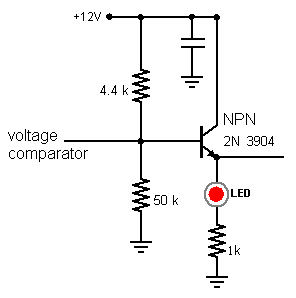
|
The driver circuit is basically an
emitter-follower circuit tuned to produce
ten volts at the emitter. The output from the voltage comparator is connected to the
base of the transistor. When the comparator output is open, current will pass into the
base of the transistor causing current to flow from the emitter. When the comparator
output is grounded, the base of the transistor is also grounded. No current will flow through
the emitter. Here is a simulation of the comparator switching the driver circuit.
UPDATE: Aug 16, 2010: I don't like this driver circuit anymore
|
Schmitt Trigger and Hysteresis
When the inputs to a voltage comparator hover near the same value, partial and rapid switching
can result in the output. A Schmitt Trigger will make the transition sharp and will
provide hysteresis. A resistor linking the comparator output to the plus input will result
in small adjustments to the plus value in response to the output state.
|
Warning: Don't let the simplicity of this give you a false sense of confidence.
There is much opportunity to misconfigure this setup. I recommend having a good understanding
of the inputs and the desired output before adding the trigger. This will
keep you from adjusting the wrong input and keep you from adjusting the input in the wrong direction.
A fairly large resistor is generally used for the Schmitt Trigger. I put way too much thought into the
consequence of this resitor bridging the input and output circuits.
I wrote the web page H
to explore the resulting resistor configuration; However, there is no adverse effects since the
resistor is fairly large.
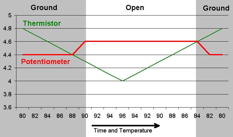
This graph illustrates this change in input voltage with a Schmitt Trigger.
The system begins with the temperature about 80 degrees. The thermistor circuit will register 4.8 volts.
As the temperature rises, the voltage output will fall.
The potentiometer circuit registeres 4.4 volts. Since the negative input is greater than the positive
input, the comparator output is grounded.
|
 |
As time progresses and the temperature rises, the voltage from the thermistor circuit drops from the
initial value of 4.8 volts. When the voltage drops to 4.4, the output of the comparator becomes an
open circuit. This causes the reference voltage of the potentiometer to change from 4.4 to 4.6 volts.
Now, the comparator sees a large difference in the input values, so it fully releases the ground.
The output state of the comparator will not change if the thermistor value hovers around 4.4 volts (hysteresis).
As the system cools and the thermistor circuit voltage approaches 4.6, the output becomes grounded.
The reference value of the potentiometer is pulled down to 4.4 volts.
The comparator now fully engages the ground.
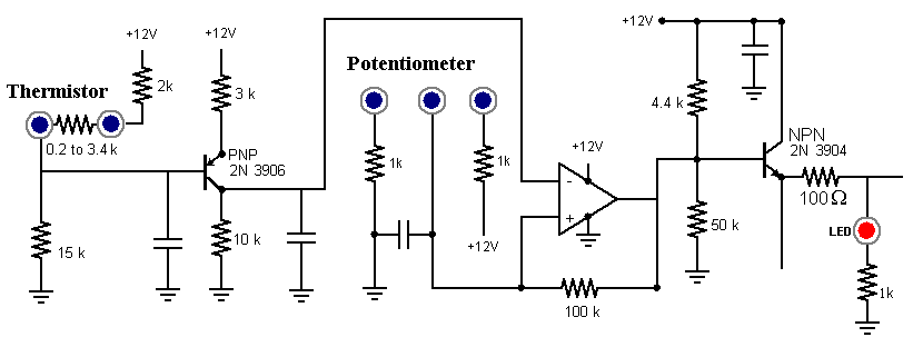
 Summary
Here is the schematic for the the thermistor circuit, the potentiometer, the comparator and driver.
 Timers
|
The driver circuit activates three timers. I configured the timers so there would be a delay
between the startup of each set of fans. This minimizes the surge of current as the fans
spin up.
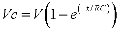
The timer is based on a resistor in series with a capacitor. As the the capacitor
charges up, there is an increase in the voltage drop across the capacitor. This value is
compared with a reference voltage. The three remaining voltage comparators on the LM339 chip
will perform the comparison.
This chart shows how many seconds it takes for the given RC system to obtain about 7.6 volts.
A simple voltage splitter using two resistors will provide the 7.6 volts for the comparator
to reference.
| Source | 9 volts |
| R (kOhm) | C (uF) |
Delay (Seconds) | Voltage |
| 150 | 10 | 3 | 7.78 |
| 470 | 10 | 9 | 7.67 |
| 800 | 10 | 15 | 7.62 |
|
|
|
|
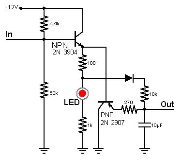
The circuit shown has a 10k resistor in series with a 10 uF capacitor. The diode prevents
current from leaking out of the RC system. The 270 Ohm resistor will provide a path for
the current to quickly discharge. This PNP transistor blocks this path while the system is
charging.
I wanted the voltage at the base of the transistor to be greater than the voltage at the
collector. (I don't know whether there is any value to this.)
The 100 Ohm resistor, with a small voltage drop, will provide two output;
One is slightly greater than the other. The greater voltage (10v) feeds the transistor
The lesser (9v) feeds the RC system, Here is a simulation of the above circuit.
|
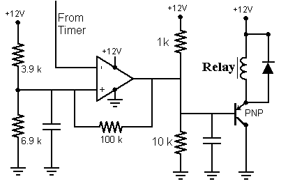
The output voltage from the timer is compared with the voltage set by a voltage divider.
The 3.9k and 6.9k resistors provide a reference voltage of about 7.6 volts.
A Schmitt Trigger links the output to this reference voltage. As the timer circuit is charging and
approaching the threshold, the Schmitt Trigger will suddenly lower the threshold. This will produce
a sharp transition in the output state.
In the actual construction, I put the Schmitt Triggers near the LM339 chip. Since the input
and output wires converge on the LM339 chip, it was convenient to add the triggers along this path.
It also helps reinforce the resistor's close association with the voltage comparator.
|
|
When the output from the comparator is open (not grounded), the 1k and 10k resistors cause current to flow
into the base of the PNP transistor. This blocks the flow of current from the emitter to the collector.
When the comparator output is grounded, the current will flow from the 1k resistor to the comparator.
Now, current will flow from the emitter to the collector and activate the relay.
Here is a simulation that uses
an LED and resistor as the load instead of the relay. A switch simulates the voltage comparator.
The power supply has three circuits capable of 1 Amp each. Each relay will switch one 1 Amp circuit.
|