| Disclaimer:The following are my notes. As I am learning electronics, I am making my notes available. I hope they will be of benefit. However, I do not guarantee the accuracy of my work. I recommend the reader exercise critical thinking.
|
Switch
Transistor Switching
|
My thermistor web page documents the exploration of a transistor as an amplifier.
I also had the need to use a transistor as a switch. This page explores some of the
math used to derive values for the resistors in such a switch.
This XLS file contains interactive examples referenced in this page.
Note that the XLS file has three worksheets.
Download the XLS file 
|
Collector
|
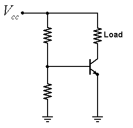
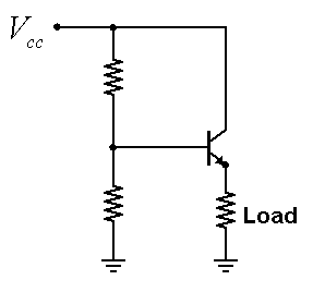
You can use a transistor to switch a load at the collector.
We are given the source voltage, the transistor parameters and the current
or resistance that describe the load.
Using these parameters, what would be reasonable values for the resistors at the base of the transistor?
There are multiple solutions to this problem. We first decide how much current should pass through R4.
I don't think this resistor is really necessary, but it does give an additional means to control
the current through the transistor. So, let's pick a small value for i4.
|
|
This figure shows the relationships used to find the values for the resistors.
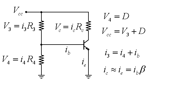
It is simple to determine the voltage of the base. It is one diode-drop (0.6 volts) above ground.
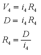
We picked a small value for i4. So, the value for R4 is readily found using R4 = D / i4.
|
|
|
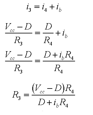
The load parameters specify how much current we need at the collector. The current
at the collector is roughly equal to the current at the emitter if the transistor has
a large amplification factor.
So, the collector current is related to the base current by the transistor's current
amplification factor.
We now know the current of the base and the current of R4. The sum of these two values
gives the current of R3.
|
|
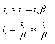
This figure shows the final steps for the derivation of R3.
In practice, you may want to push more current to the base than indicated by these equations.
These relationships would then be altered by substituting a multiple of ib for ib.
A similar loading of the base would happen if R4 were removed from the design.
Click here for a simulation
of the above circuit.
This simulation uses an on-off switch to simulate the effect of a voltage comparator used
to initiate the switching.
(Simulation program from http://www.falstad.com/circuit/)
|
|
Emitter
|
You can use a transistor to switch a load at the emitter.
We are given the source voltage and the transistor parameters.
Specifications are given for current or resistance and voltage of the load.
Using these parameters, what would be reasonable values for the resistors at the base of the transistor?
|
|
The value for ie is easily obtained from the load parameters.
From this we can determine ib as in the previous example.
The voltage Ve implies our base voltage, V4, must be
one diode-drop greater than Ve: V4 = Ve+D. The value for V3 is then V3 = Vcc - V4.
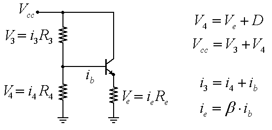
There are multiple solutions to this problem. We will pick a value for R4 and then determine
the value for R3 that will meet the problem specifications.
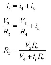
The current for i4 is easily obtained by i4 = (Ve+D)/R4. Now, R3 can be
obtained using the the current relationship i3 = i4 + ib.
Click here for a simulation
of the above circuit.
This simulation uses an on-off switch to simulate the effect of a voltage comparator used
to initiate the switching.
(Simulation program from http://www.falstad.com/circuit/)
|


