| Disclaimer:The following are my notes. As I am learning electronics, I am making my notes available. I hope they will be of benefit. However, I do not guarantee the accuracy of my work. I recommend the reader exercise critical thinking.
|
Emitter Follower
I spent the past couple of days trying to understand the Emitter-Follower circuit.
I thought it would be easy to understand, but I found it very non-intuitive.
Now that I think I understand how it works, I wanted to document my approach to this problem.
|
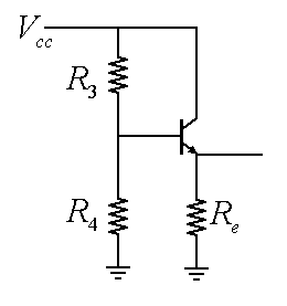
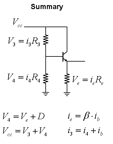
Given the following circuit with voltage source Vcc and resistors R3, R4 and Re,
what can we determine about the current?
We are also given the hFE or Beta (B) of the transistor. The goal is to obtain equations for the
currents in terms of R3, R4, Re, B and Vcc.
|
|
|
|
|
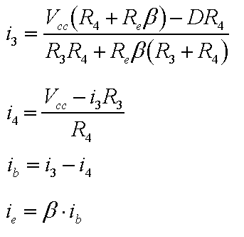
The results are summarized with these equations. Now I see why the results were not intuitive.
This XLS file will calculate the values for the currents.
Download the XLS file 
Click here for a simulation of the above circuit.
(Simulation program from http://www.falstad.com/circuit/ simulator.)
The rest of this page illustrates the derivation of these equations.
|
|
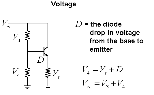
We can use Kirkoff's voltage law to map out the voltage drops. The letter D represents
the inherent voltage drop between the Base and Emitter of a transistor.
This is called the "Diode Drop". The value is generally between 0.6 and 0.7 volts. I simply
use the variable D for this quantity.
|
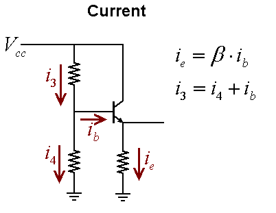
Kirkoff's current law relates the current going to the base of the Transistor.
The transistor amplification factor hFE (or Beta) gives a relationship for the current
going through the transistor. Just as the diode drop (D) relates the voltage across the
transistor, the beta (B) relates the current.
|
|
Putting these together with Ohm's law and we have all the equations we will need to derive the values
for the currents.
|
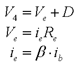
We start by examining the bottom part of the circuit. The voltage across R4 is the same as the voltage
at the base of the transistor. This the same as the diode drop plus the voltage at the emitter. This
gives the first equation.
The voltage at the emitter is the same as the voltage drop across Re. This is our second equation.
The amplification factor is represented with our third equation.
|
|
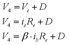
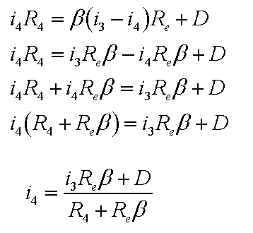
Performing these substitutions, we have the following.
|
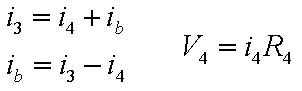
The current relationship allows us to replace ib with i3 and i4. The quantity V4 will be replaced with
a relationship involving i4.
Our previous equations just got a little more complicated. But we end up with an expression
relating i3 and i4. All other quantities in the expression are known quantities.
|
|
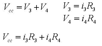
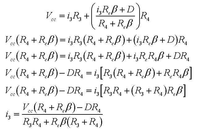
The next step begins with the voltage drop across R3 and R4. This produces
an equation involving i3 and i4.
We substitute our previous value for i4 into this equation.
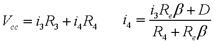
We now have an expression with only one unknown quantity, i3.
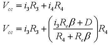
Solving this for i3 is not very pretty, but I think it is our answer:
Now that we know i3, we can use the relationship for the voltage drop across R3 and R4 to find
i4.
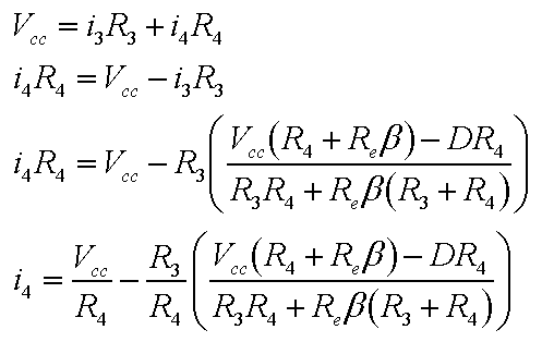
The rest of the current values are easily found. Given that i4 is rather unwieldy, I will just
outline the rest of the equations.
The current relationship, i3 = ib + i4, gives us the value for ib.
The value ie comes from the current amplification equation ie = B * ib.
|


