| Disclaimer:The following are my notes. As I am learning electronics, I am making my notes available. I hope they will be of benefit. However, I do not guarantee the accuracy of my work. I recommend the reader exercise critical thinking.
|
Thermistor
Thermistor and Common-Emitter
|
My thermostat circuit design use a thermistor to detect the temperature change.
I roughly measured the thermistor relative to a thermometer and charted the relationship.
The interesting values of the thermistor range from 200 Ohms to 3.2 kOhms. This change
in resistance will result in a voltage signal fed into a voltage comparator.
This XLS file contains interactive examples referenced in this page.
Note that the XLS file has three worksheets.
Download the XLS file 
|
| Temperature (F) | k Ohms |
| 16 | 3.4 |
| 50 | 2.0 |
| 60 | 1.8 |
| 95 | 0.8 |
| 130 | 0.4 |
|
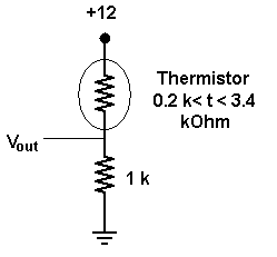
The simplest way to map a resistance change to a voltage change is
to use Ohm's law (V=IR). If I have the thermistor Rt in series with
a fixed resistor R, then the voltage drop across the fixed resistor will vary
dependent on the temperature: V*R/(Rt+R). However, this change in voltage
has an associated current that, at times, may be high. The spreadsheet shows
the current could be up to 10 mAmps and power up to about 40 mWatts.
|
Bad Design
|
I wrote the Emitter-Follower web page in preparation for this project.
The principles of the Emitter-Follower allow us to control the current and voltage at the emitter.
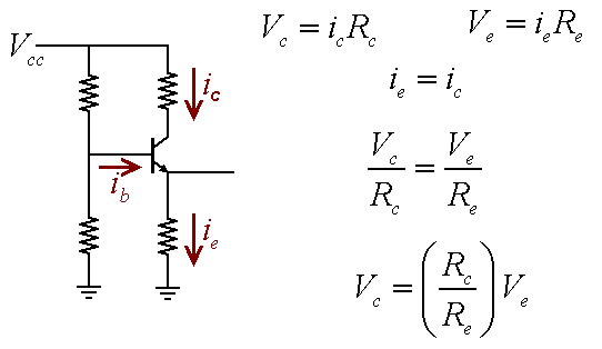
The Common-Emitter amplifier circuit is closely related to the Emitter-Follower.
The Emitter-Follower amplifier has a resistor at the emitter (Re),
but the Common-Emitter amplifier has an additional resistor at the collector (Rc).
Since the current through the collector and emitter are roughly the same, we can derive
a proportion relating the voltage drop and resistance for Re and Rc. The result is
a voltage amplification given by Vc=Ve(Rc/Re). Note: Text books
relate this amplification factor to the voltage change at the base (Vb) which is roughly
equivalent to Ve. In this case, it should be remembered that the change in Vc is in
the opposite direction of the change in Vb.
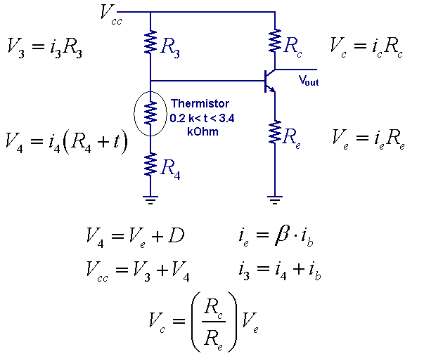
The new design of the thermistor circuit uses a Common-Emitter amplifier. The spreadsheet
shows the output voltage for the range of thermistor values. The spreadsheet supports
customized values for R3, R4, Re and Rc. My approach to the problem was to select Re and
R4 as small values (1k to 4k), the value for Rc is a few times Re, and the value for R4 is
many times Re. The large R4 value compared to the small R3 value will set a low
voltage reference for the base of the transistor. The small Re value compared with the larger
Rc will produce the voltage gain. Be sure that the sum of Vc and Ve does not exceed
input voltage Vcc. You cannot create free energy this way ;)
|